
The previous CMOS Synthesizer project I designed was created for demonstrating Synthesizer Basics when I was presenting the synthesizer training courses for a previous employer. As a traianing aid it is almost perfect; the loop filter can be adjusted until the loop goes into self oscillation and the VCO can be set to almost any frequency. Now that I am building synthesizer circuits for serious use it is time to update the project.
The super, new, miracle, improved version has many new features that make it suitable for the frequency generator for hamradio or other "on-the-air" applications. The lock time of this synthesizer is now too good so it may not be a good idea to use it in a transmitter/receiver when a fast TX/RX changeover is needed. The project improvements include:
Having said all that, I still recommend the original training aid project and an oscilloscope as a tool for learning the basics of synthersizer operation. Componenents out of practical ranges can be selected to see what they do.
The basic circuit remains exactly as before, but all the selectable links have been removed. These links were included on the original version to show my students what would happen if a particular compnent was changed. Useable link settings have been a continuous source of e-mail questions for me! The damping resistor has been de-coupled to reduce the reference frequency modulation.
The loop filter has added filtering (0.1uf capacitor), although still quite rudimentary. An output buffer stage has been added to provide an output point and at a usefull level for most aplications, over 200mW. You will still need to use a low-pass filter if you wanted to connect the oscillator to an antenna, PA or receive mixer. This is not included on the PCB. The link between the VCO and CD4059 divider has been engineered as a wire link on the PCB. This means you can remove it and use an external VCO with an in-built prescaler, allowing generation of frequencies of up to 150MHz with the next PCB I shall be posting.
I mentioned spectral purity. If you consider the output signal with a simple loop filter, the RF spectrum looks something like this:
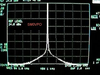
Here you can see that there is a wide "skirt" near the bottom of the peak. By changing the timing and dampling resistors to 100K and 3K3 then decoupling the 3K3 with a (relatively) small capacitor, the close-frequency spectrum looks more like this:
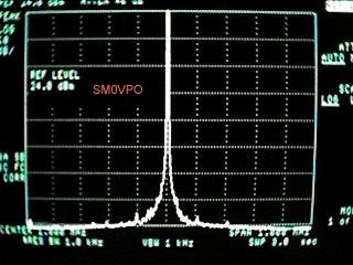
Now that looks a lot better! Not perfect, but certainly a huge improvement. The spurious levels were originally quite low but now they are much cleaner. In practice, if you listen to the signal with an NBFM radio receiver (FT101 160metre band FM mode) you would hear the 1KHz reference frequency, especially after the loop received a minor disturbance. Now that has almost dissapeared. It is still far from perfect, but now it is acceptable. Ok, so we have improved the frequency purity close to the centre frequency, but what about that low- pass filter I mentioned earlier? The output of a CD4046 VCO section is a square-wave and that is festooned with harmonics. After all, it is a square-wave. Odd harmonics are strong but the even harmonics are a little weaker:
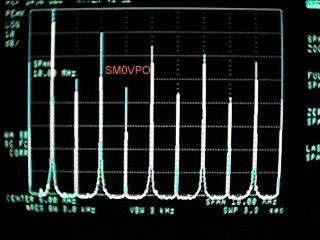
If you want to transmit this signal or use it as the LO an a decent receiver then you MUST use a low-pass filter to remove all the crap above the wanted frequency. There is, of course, no reason why you cannot use a band-pass filter to select a harmonic. What you do with the output of this basic synthesizer is up to you. I have not (yet) photographed the final synthesizer, but here are a fiew views of the prototype before I added the output buffer/amplifer.
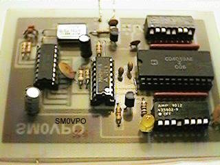
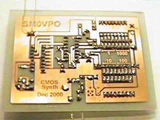
I have included on the PCB thermal breaks around all component leads soldered to large lands of copper. As you can see, the only DIP switches on the board are the frequency selection switches. The reference frequency is fixed at 1KHz and this is derived from a 4096KHz crystal and divided by the CD4060 integrated circuit divider. So what is next? You build this interesting synthesizer for yourself, that´s what! I shall shortly post the VHF VCO/Prescaler board so you can add to the project. The VHF VCO board uses coils fabricated on PCB, but there are several PCB coils for different bands. But, you will just have to wait for the project. Just bookmark Harry´s Homebrew Homepages and come back regularly.
One last final point, the 8x resistor array is now quite expensive here in Sweden, over $7 each!! I will NOT pay that. So I have made a PCB that is mounted vertically to support them. I will not add the PCB to the Download pages, I may as well just put it here. I think it is self explanatory and I am sure you will work it out. Click on the pictures then save the image from the new page.
Note that the views are ALL from the component side. If you print the board with the scale, then the numbers should be written the correct way round on the final PCB copper foil.
Have fun, de HARRY.
Return to INFO page