CMOS RF SYNTHESIZER
by Harry Lythall - SM0VPO

The Synthesizer
One of the most interesting projects to work with is that of a
synthesizer that can accurately gnerate desired frequencies. This
synthesizer uses just three CMOS chips and one PNP transistor. It
is a fact that the transistor may be the hardest component to get
in some parts of the world!! The synthesizer will generate a 3:1
frequency range anywhere from 300Hz to 4,000,000Hz (4MHz). Using
the components shown you can feed the synthesizer with up to 12vDC
but with only 9vDC the synthesizer may not achieve more than 3.5MHz.
Tye lock-range of this synthesizer is about 10:1 or so.
The Reference Oscillator
The CD4060 reference oscillator divides a crystal reference oscillator
sucessively by two. From each stage we can select a frequency that is
half the value of the previous frequency. The reference frequency of
the synthesizer is multiplied by the programmeable divider divide rate
to give the final frequency. If our reference frequency is 1KHz then the
final output may be programmeable in 1KHz steps. This is quite convenient
for a decimal programeable divider. Divide by 1000 = 1000KHz, divide by
1001 = 1001KHz etc. You could also select a crystal that would give you a
100Hz output then you could select frequencies in 100Hz steps. Divide by
1000 = 100KHz, divide by 1001 = 100.1KHz etc. Here are reference
frequencies you could use for different oscillator crystal frequencies.
CRYSTAL/REFERENCE FREQUENCIES (FROM 4060)
| Crystal | Q8 (pin13) | Q9 (pin15) | Q11 (pin1) | Q12 (pin2) | Q13 (pin3) |
|---|
| 32.768KHz | 64Hz | 32Hz | 8Hz | 4Hz | 2Hz |
|---|
| 256KHz | 500Hz | 250Hz | 62.5Hz | 31.25Hz | 15.625Hz |
|---|
| 512KHz | 1KHz | 500Hz | 125Hz | 62.5Hz | 31.25Hz |
|---|
| 819.2KHz | 1.6KHz | 800Hz | 200Hz | 100Hz | 50Hz |
|---|
| 1024KHz | 2KHz | 1KHz | 250Hz | 125Hz | 62.5Hz |
|---|
| 1638.4KHz | 3.2KHz | 1.6KHz | 400Hz | 200Hz | 100Hz |
|---|
| 4069KHz | 8KHz | 4KHz | 1KHz | 500Hz | 250Hz |
|---|
| 8192KHz | 16KHz | 8KHz | 2KHz | 1KHz | 500Hz |
|---|
| 16384KHz | 32KHz | 16KHz | 4KHz | 2KHz | 1KHz |
|---|
Remember that the programable divider will only divide up to 15999
and this limits the maximum frequency you can get out of this
synthesizer. With a 100Hz reference frequency you can only get a
maximum of 1.5999MHz. With a 1KHz reference frequency you can program
up to 15.999MHz which is beyond the range of a CD4046. Incidentally,
a 32,768Hz wrist-watch crystal will give you 2Hz so the synthesiser
will generate from 6Hz up to 31,998Hz in 2Hz steps.
The VCO
The 4046 has a wide-range Voltage Controlled Oscillator (VCO) which uses
C1 and R3 to determine the frequency. C1 is selected by LK2 and I used
33pf, 47pf, 68pf and 100pf. R3 is selected by LK5 and I used 4K7, 10K,
33K and 100K. The 10K resistor from pin 12 is an offset resistor which
may be omitted. I only used it to push the VCO up to 4MHz which is about
the maximum you will realistically get from a CD4046. The 74VHC4046 is
supposed to go up to someting like 20MHz.
There is no reason why you cannot use an external VCO, such as a VHF
oscillataor with a divide by ten prescaller. This should enable you to
generate up to about 159.99MHz in 10KHz steps.
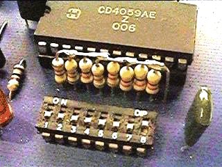
Programmable Divider
The output of the VCO is divided by a programmed figure in the 4059 IC.
I just used two 8-pin DIP switches on the PCB but there is no reason why
you cannot use "BCD thumbnail" switches. Each digit is in the form of
Binary Coded Decimal (BCD) and so the range of each digit is 0 to 9. The
1000's digit however may be programmed up to 15 (F in hexadecimal) so the
maximum divide rate is 15999. The minimum divide rate is 3 so that with
a 100Hz reference oscillator the minimum output is 300Hz.
Phase Detector
The reference oscillator and the output of the programmable divider are
both fed into the twin phase detectors in the 4046. One of these outputs
(pin 13) gives a HIGH, LOW or TRISTATE (high impedance) levels which
indicates whether the programmable divider output is above, below or equal
to the reference frequency. This is used to control the VCO frequency and
complete the loop. There is a second phase detector but this is little
more than an Exclusive-OR gate. I have used this to give a loop locked
indicator via the LED and the BC557 (PNP) transistor.
Loop Filter
The output of the phase detector is fed via R1 (10K, 33K, 100K and 330K
selected by LK3) to a capacitor to form the loop filter. If the loop filter
time constant is too short then FM modulation will be removed. If too long
then it will take too long for the loop to lock onto a new frequency. There
is also a dampling resistor R2 (1K, 3K3, 10K and 33K) which is selected
by LK4. The loop damping resistor should be included to prevent loop
over-correction. This would result in the VCO constantly swinging above
and below the correct frequency.
Output Signal
The PCB does not give any particular output socket since it was designed
for training dealer staff and was only to be viewed with an oscilloscope.
A high-level buffered output is available from pin 10 of the 4046 VCO but
this must have a load resistor of 10K to ground. The output is a square-wave
with odd harmonics extending throughout the HF spectrum. Here is a spectrum
display from the prototype - 0 to 20MHz:
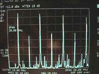
As you can see, there are both odd and even harmonics throughout the HF
spectrum with the odd harmonics being the strongest. This means that you
will need to filter the output if you intend to use it for transmitting
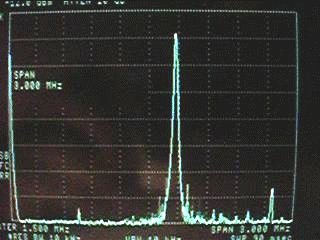
or receiving. A closer view of the spectrum, also at 1.8MHz centre
frequency shows the output to be relatively clean:
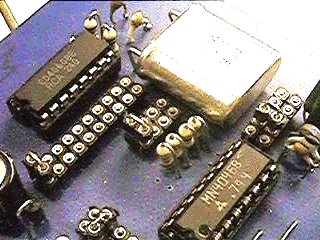
Construction
The completed synthesizer PCB is 108mm x 64mm and has only battery
(and output?) connections. I fitted all three ICs to sockets even
though modern sockets cost more than the CMOS chips (I am VERY old-
fashioned, I even like to see girls in black seamed stockings!).
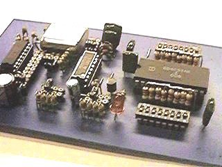
Because this unit was used for training I needed to adjust some
of the settings so I used header sockets and U links. In this way I
could select any clock frequency, VCO parameters and loop-filter
settings I wanted.
Frequency Programming
I set the frequency by means of two eight-pin DIP switches. Note that
the place values of the switches are 1 2 4 8 from left to right EXCEPT
the fourth (most significant digit) which is backwards: 8 4 2 1.
Let us assume I want to generate the frequency 1.815MHz. With a 4.096MHz
crystal I set the following links and DIP switches. Note that the MHz switch
is backwards.
| LK1 = 1KHz (Q11) | LK2 = 33pf | LK5 = 4K7 |
|---|
| Loop filter | LK3 = 100K | LK4 = 10K |
|---|
| DIP-1 (5KHz) | 1 & 3 = ON | 2 & 4 = OFF |
|---|
| DIP-2 (10KHz) | 1 = ON | 2 3 & 4 = OFF |
|---|
| DIP-2 (800KHz) | 8 = ON | 5 6 & 7 = OFF |
|---|
| DIP-1 (1MHz) | 8 = ON | 5 6 & 7 = OFF |
|---|
Setting Links
LK3 and LK4 are entirely optional. If LK4 is omitted and R2 is made a
total short circuit then the circuit will never stabilise but oscillate
up and down the band. LK4 should be a mirror of LK3. LK3 sets the loop
time constant. If you add DC blocked AF to the VCO voltage (4046 pin 9)
via a 270K resistor then you will be able to generate an FM signal. With
LK3 set to 10K then AF below about 1KHz will be removed (the loop feedback
will see modulation as a frequency error). With LK3 set to 1M0 then the
loop will take an eternity to stabilise but will give good quality
modulation down to to about 100Hz.
The PCB
A printed circuit board is available but I drew the artwork before I had
a computer so I used drafting pens with old fashioned ink on good old
tracing paper. I have scanned my PCB Artwork which works, but I have not bothered to tidy it up. I
have not yet drawn a component overlay as I think that it should not be
too difficult for anyone of modest intelect to identify the component
locations. Anyway, you can not complain, it's for free!!
Did You Know that ...
To make an RF VCO that works in the VHF spectrum, forget about buying
those expensive VariCap diodes - you don't need them. Ordinary high
voltage Zener Diodes work. A 20v zener diode operated at 1v to 13.8v
exhibits a capacitance of typically 10pf to 2pf as the voltage is varied.
I have even used this effect to make a 5.0MHz - 5.5MHz VCO for this
synthesizer, just as an experiment.
Dont forget to visit my messageboard if you have any questions about this or any other project. I always look forward to receiving feedback, positive or negative. You do not have to register to post messages.
Very best regards from Harry Lythall
SM0VPO (QRA = JO89WO), Märsta, Sweden.
EA/SM0VPO (QRA = IM86BS), Nerja, Spain.
Return to INFO page