
It is really interesting that new ideas and project seem to give me more project idea spin-offs. This project is no different. While designing my new VHF-HF Transverter project I needed a modest power local oscillator at 130MHz. I initially thought about a low power of around -7dBm (5mW), but there was no problem with higher power, in fact a 200mW oscillator is good for a high-level signal conversion. This oscillator also had to be voltage-controlled since it is controlled by a Phase-Locked Loop (PLL).
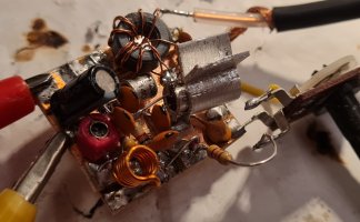
The thought occured to me that if you remove the mixer stage and the PLL, all that remains is a 200mW, VHF FM transmitter. Because it is voltage-controlled, it means that Frequency Modulation is already available. The result has been tested on both bird's-nest (more like a rat's nest) and on a prototype Printed Circuit Board (PCB). So this project is the 180mW - 200mW VHF FM Transmitter that was developed as a part of the transverter. It is the stand-alone, VHF FM transmitter.
I still occasionally get the e-mail question "What range has the transmitter got?". That is a good question! It is a bit like asking "How long is a piece of string?". The answer is that it can be very short or exceedingly long; somewhere between 50m and 100,000m, depending on a number of different things. If you want more detailled information then take a look at this article pathloss_42.htm (opens in a new tab) that gives examples from 0.1mW to 100 Watts, in 10dB steps.
Here is the circuit diagram of the VHF FM transmitter. The whole transmitter is built on a single PCB, unless you prefer the rat's-nest version. It is a fact that rat's nest construction looks childish, ugly and amateurish, but RF circuits built in this manner usually out-perform many nice, posh printed circuit board designs. This is because on a PCB, components have wire legs that reach down to the copper tracks on the board. The copper tracks have inductance, and because they are so close they also have more stray capacitances between the tracks. Rat's nest, on the other hand, uses direct point-to-point wiring without the copper tracks. This perfect for RF circuits. But it would be difficult for JVC to sell you an amplifier using rat's-nest construction. It also has to be artistic and beautiful.
It is a bit like Air-Traffic Control: If you were to fly direct in a straight line from Stockholm Arlanda in Sweden, to Charles De Gaulle airport in france, the chance of you ever hitting any other aircraft, at the same height, at the same time, and perfectly aligned with your flight-path, are so infinitesimally small that you can forget about it. The only aircraft you are likely to meet could possibly be the Paris to Stockholm flight travelling in the opposite direction, but North-bound and South-bound air-traffic should be at odd or even heights anyway. Air-Traffic controllers herd all aircraft traffic into very narrow air-lanes, thus bunching them together tightly, just like the tracks on your PCB. Air-Traffic controllers then justify their high sallary by trying to keep the aircraft apart and prevent them from bumping into each other. It is interesting that air-lanes have to be colour-coded so that it is easy for pilots to understand.
But let us continue with the PCB version, anyway. It looks pretty 😉.
The oscillator stage comprises TR1, which covers covers 80MHz to 120MHz, set by L and the 20pf variable tuning capacitor VC. L is 6.5 turns and covers the complete FM band with good modulation sensitivity. If you have a high-level input, for example from an MP3 player, or cassette tape player, then you may need to attenuate the audio to prevent over-modulation.
VC and L are coupled via 10pf to a 16V Zener diode. In case you are unaware, Zener diodes are beautiful Variable Capacitance (Varicap) diodes, and they are a lot cheaper. The Zener-Varicap diode is DC-coupled to the regulated 0 to 9.1v voltage-regulator, D1 and potentiometer RV. RV is in effect a fine-tuning control and should ideally have a logarithmic taper. This will give you a smooth and even fine frequency control of about 3 MHz, or more.
Audio signals are fed into the Varicap diode, which modulates the transmitter frequency. There is no pre-emphasis provided, but if your audio source has tone controls then you can screw up the treble a bit. Otherwise the modulation is linear from about 20Hz to well over 100kHz. This makes it ideal to use with my 222-Stereo encoder project (opens in a new tab). Pre-emphasis is included in that project.
TR1 is a conventional Colpits oscillator, with two 10pf feedback capacitors between TR1 base, emitter and ground. With the resistor values given, the emitter of TR1 should be around 3V DC. If you use any other transistors then you may need to change the value of the 27K resistor feeding TR1 base. The values should be high since they also present an impedance load on TR1 base.
TR2 is a power amplifier that is directly connected to TR1 emitter. TR1 therefore provides the DC bias for TR2. This direct coupling is not frequency conscious and also gives zero signal loss. This is why TR1 biasing is a bit critical. The emitter of TR2 has a low value resistor, but the 22pf capacitor lowers the decoupling impedance at RF to increase the gain of the amplifier. You can change this to 33pf if you want more output power, but not higher. If you have a 1nf capacitor here then TR2 input impedance will be so low as to stop the oscillator. 22pf also leaves some Negative Feed-back so that the gain is more dependent on component values rather than transistor characteristics. This makes the circuit repeatable.
TR2 draws about 50mA, which means that the dissipation at 12V is in the region of 600mW. The 2N2369 is rated at up to 200mA, but it can get hot if it is not fitted with a heat sink. I used a 4cm x 1cm bit of thin copper, or aluminium plate, and wrapped it around a 4mm drill-bit, leaving 2 "wings" to radiate the heat. The material I used was 1.2mm thick, which is really a bit too thick. 0.5mm would be perfect and easier to work with. This proved to be ample heat-sinking for 100% continuous running. That is to say that my two prototypes did not start smoking.
TR2 collector uses a wide-band, 1 : 1.5 transformer, to change the impedance from 32Ω to 50Ω. That is to say, 6 turns of wire on a ferrite ring, with a 9-turn secondary winding. The ferrite ring I used is RND 20165-00182 (opens in a new tab) from elfa.se. The ferrite is 10mm diameter, with a 5mm diameter hole, and is 5mm thick.
The actual grade of ferrite in this application is not particularly critical, but it does follow my Ferrites Rule-Of-Thumb (opens in a new tab).
It is unusual to have ferrite rings in a VHF output transformer. The usual method of matching VHF power amplifiers is to have a resonant capcitive/inductive output circuit. This requires tuning in the event you change frequency. This circuit does NOT need any tuning, and the output is almost flat (< ±1dB) from 80MHz to 120MHz. Note that an output Low-Pass Filter (LPF) is always needed with any transmitter. So let us consider output filtering:

In the article pathloss_42.htm you will see that the range may be typically 5km from gound-to-ground, but if you go up in a baloon to 30,000 feet (10km) then the range could be as high as 100km. This means that you could cause interference to aircraft communications over unexpectedly large distances (118.000 to 136.975 MHz). Because aircraft are herded into narrow air-lanes, if you interfere with one of them, then many aircraft are likely to hear your Barry Manilow collection. If you are broadcasting Barry Manilow then pilots are likely to be your ONLY listeners. They will not appreciate it! If your transmitter does interfere with aviation, or any other services, then this is bad news for pilots and you can expect some seroius trouble. You should ALWAYS use a band-pass filter between a transmitter and the antenna.
In this particular transmitter, the oscillator is at the output frequency so you could use a simple low-pass filter (LPF) instead of a band-pass filter (BPF). A simple 7-pole low-pass filter can consist of two inductors and three capacitors. A simple butterworth filter with a "knee" at 108MHz would be flat up to about 90MHz, but would give a loss of 3dB at 110MHz and only 20dB loss at 140MHz. In other words, it would almost halve the transmitter wanted output at 108MHz, and provide insufficient attenuation in the aircraft band. There are better filters to use:
As you can see, the Bessel LPF is nothing to have and has high losses just before the cutoff. The Butterworth is great for the usual harmonic filter. This trasmitter project, however, needs something better due to the frequency proximity to the VHF aircraft band. The transmitter itself is very clean on the spectrum analyser, but if there is any overdriving, or construction differences, then there could be some rubbish close to the operating frequency.
A 7-pole Chebyshev LPF would be a minimum requirement in this application, so I have chosen the Cauer-Chebyshev Elliptic LPF variant. This will give a theoretical 20dB reduction of spurious output at 118.8MHz. This elliptic filter has three sharp dips in the stop-band, which increases the slope at the cutoff frequency. The measured response was about -60dB at 135MHz. I will see if I can borrow a VNA to get a response curve, but I only have an RF signal generator, spectrum analyser, and have to plot it myself. The prototype filter did follow the graph very closely.
I have given calculated the values for the eliptic LPF output filter, and the PCB is designed to have two capacitors fitted to make-up each each of the seven odd-ball capacitors, so you can get very close to the calculated values using standard values. C3, for example (49.382pf) can be a 47pf in parallel with a 2.2pf, which will give you 49.2pf (calculated value = 49.382pf). Use capacitors with a very close tolerance. The three coils are all 3-turns of 0.8mm diameter magnet wire, but you need to get the turn-spacing accurate. Measure from the center of turn 1 to the center of turn 3. L1 = 1.6mm, L2 = 2.4mm and L3 = 2.3mm. All three coils have a lead space of 5mm so that they fit on the PCB. All three coils are wound on a 6mm drill bit.
The filter is mounted on the PCB with a good copper ground. It will be improved by soldering a grounded metal screen hood over the filter. You can usually rob old mobile telephones, or old external hard-disk cases, for thin tinned metal that is easy to cut with scissors and easily soldered on the copper PCB.
In my opinion it may be wise to assemble and test the output filter before you assemble the rest of the transmitter. Then you can test and align the filter, then concentrate on the actual transmitter.
The usual method of aligning a filter is to use a spectrum analyser with a tracking-generator to sweep the band and watch the frequency response. If you do not have such analyser then do not give up hope. There are other ways. All you need is a frequency counter and some means of looking at the RF waveform. For viewing the signal a simple 200 MHz oscilloscope is good enough, but even a 100MHz scope will still give a usable display of the RF signal level at 130MHz. You can alternatively use an RF voltmeter to look at the output levels. If you inject 1V of RF at the input to the filter then you need to see an RF signal of 1mV.
Remove the WLK (test) wire link on the board from the transmitter output to the filter input, and use a signal generator to inject an RF signal, at least 1V RMS (about +13dBm, 20mW). Terminate the filter with a 50Ω dummy load (a 47Ω resistor is ok, but use two 100Ω resistors in parallel). Sweep the generator from 90Mhz to 300MHz and watch the RF level on the oscilloscope. You will see that the loss of the filter is quite low at 90MHz, but with the component values given, it should begin to fall over about 107MHz. There should be three very deep notches at 140MHz, 160MHz and 260MHz.
You can adjust the spacing of the coils L1, L2 and L3 to make sure the notches do indeed occur at the correct places in the frequency spectrum. These notches should be about 90dB (1/1000th of the input voltage). L3 adjusts the 130MHz notch, L2 adjusts the 160MHz notch and L1 adjusts the 260MHz notch. They should be adjusted in the sequence L3 first, L2, then L1 last. Repeat this again because adjusting one coil may have a slight effect on the other two notch frequencies.
Note 1: If you use an uncalibrated oscilloscope then you can easily check the filter loss by comparing the input voltage with the output voltage. The loss in the filter should be less than 25% of the power (10% of the voltage amplitude), which corresponds to about 1dB.
Note 2: If you have already assembled the complete transmitter, then you should NOT have it powered up while you are aligning the filter.
When the filter is aligned, fit the WLK/Test link.
The prototype was originally built on a bit of waste PCB, as in the photo at the top of this page. I took absolutely no time to make it neat as I only wanted to check the design before I laid out the PCB, so I offer absolutely no apologies for beauty. The PCB has been assembled for the VHF-HF transverter board, and it worked even better than the bird's-nest (that's unusual). I have laid out a PCB for this project.
The PCB itself measures 2.0" x 2.3" (51.5mm x 59mm), single-sided. The above drawing is 50% of the drawing scale but you can view and download the full-size hi-res PCB if you click on the picture above (opens in a new tab). If your graphic printing program (eg. PaintShop Pro) has a default of 72 pixels/inch (28.346 pixels/cm), then in the "Print setup" menu, set the print resolution to 24%. If there is a "Use printer resolution" option then select it. It will give you a 51.5mm x 59mm printout. The PCB was drawn in Proteus 7 Professional. The hi-res circuit board is 4x the normal size, so if you want to print it then do NOT resize the drawing or you will loose a lot of detail. You can alternatively import the picture into an MS-WORD document, switch ON the ruler and set the picture to the correct size to print to 100%.
Note that the text SM0VPO on the PCB copper side should be the correct way round when read from the copper-side.
The inductor L is wound using 0.8mm diameter enamelled wire on a 4mm diameter drill bit. Be sure the turns are very close-spaced; touching is best. It is worth taking a bit of time to get the coil exactly as you can see in the photograph. If you have difficulties getting below 90MHz then you can put a 4mm diameter ferrite bead in the coil. If you do this then you may will find the modulation sensitivity will increase. A coil this small and so few turns may not give you any microphony problems. If you do notice any microphony then a little blob of candle wax on the coil will stop it.
Note that most ceramic capacitors on the PCB have three holes printed. This is so that you can select either 2.5mm or 5mm lead spaced capacitors. The 10pf and 22pf capacitors should be NPO types (usually have a black painted spot at the top of them). The preset tuning capacitor (20pf) VC may be 2-pin or 3-pin types, and there is space on the board for either variant. You may have to increase the hole size to 1mm for some variable capacitors. The "Fine Tune" potentiometer RV is also generous with space so that you can have almost any miniature preset potentiometer.
As usual, stuff all the horisontal components first, then the vertical, and the transistors last. Fit the heatsink on TR2 before you power-up the transmitter. Check the supply has no short-circuits, and check that the emitter of TR2 is not shorted to ground. 2N2369 is a fantastic VHF transistor, but it is a bit unforgiving and easy to burn. Don't worry about that, "just look at the plumage" (google it 😉).
One little point that needs explanation is the one wire-link on the PCB, marked WLK/Test on the component overlay. This is the connection from the transmitter to the Low-Pass filter. For testing purposes, you can connect to either the transmitter output, or the filter input, before fitting the wire link.
Set RV to 50% and double-check there are no short circuits. Be sure that your two diodes are the correct way round.
Set your Power Supply Unit (PSU) to 6V DC and the current-limiting to 50mA. If you do not have a PSU with current limiting then use 4x AAA cells and an old pocket-lamp bulb, the ones with a tungsten fillament. If the lamp lights then you have a short. If not then you should get about +7dBm (5mW) out from the transmitter. Check the voltage at TR2 emitter is about 1V or somewhere around that.
If all is well then you can increase the voltage to 13.8V (slowly) and watch the output rise to around +23dBm (200mW) or more. Measure the voltage across the 9.1V Zener is in fact 9.1V DC. Now tune an FM receiver to around 105MHz, between any other stations. Adjust the variable capacitor VC slowly until you get a nice "thump" from the radio speaker, and a reduction of noise on the radio as you tune through it. Use the RV control to fine-set the frequecy to the radio. Connect the MP3-player (cassette player or gramophone, depending on how old you are) headphone output into the AF-in terminals. Adjust the MP3 player volume so the radio volume is about the same volume as other broadcast stations. If you really do want to broadcast Barry Manilow songs then you should set the modulation even lower - ±0kHz would be a good starting point 😉.
Airband - Aircraft frequency information.
Aircraft Radio Frequencies used for Aviation - RF Wireless World.
The Barry Net - Barry Manilow fan club (for masochists).
I hope that this project has given you some "food for thought", and hopfully persuaded you NOT to broadcast Barry Manilow music. You can always e-mail me at harry.lythall@[my domain].com. You can even use oeieio@hotmail.com or hotmail@sm0vpo.com as they are both valid e-mail accounts for me 😉 although I would prefer that you visit my messageboard if you have any questions about this or any other project. I always look forward to receiving feedback, positive or negative 😊
Very best regards from Harry - SM0VPO
Return to INFO page