
Rule of Thumb: This supposedly dates back several hundred years, long before the Internet was invented. A man could beat his wife with a big stick, providing the stick was no thicker than his thumb. I wonder if there was a "Rule of Fryingpan" for wives to beat drunken husbands coming home from the pub? There is no factual evidence to support either ROT or ROF.
There have been many comments about using ferrite rings in many of my projects. The most common question is "Harry - What grade of ferrite did you use for this project?", or "how did you estimate L and C values for 9MHz". Answer: For a quick L/C estimate I have an old Rule of Thumb, but for ferrites I used to just put my hand in the junk-box and saw what came out.
I had loads of ferrites of different (unknown) grades, so I selected the grey ones that looked about the right size for the power. In my experience the grey ones are all good enough for RF, up to about 30MHz, or more. Under 30 MHz one only needs to evaluate how many turns for any given inductance. In most projects you can use just about any ferrite ring for HF work, but the ferrites below are easily obtainable and I think I should try to standardise so that my projects are easy to reproduce.
If you just want to make a balun or RF choke, then the actual inductance is not so important. A balun for the HF bands usually can have a frequency ratio of about a 10:1.
These two facts are somewhat contradictory, but the point is that almost any ferrite can give a 20:1 frequency ratio, or more, in a balun. For 3MHz to 30MHz you have about 90% chance of just guessing a good value. The art is to get it somewhere in the middle. It only takes 5 minutes to wind a balun, so you can always guess and adjust if the high or low frequencies could be improved.
If a ferrite gets hot then it is permanently damaged. But the dead ferrite will give you an idea as to the power handling for that particular ferrite. They should not even get warm. In my experience the power handling is related to the volume of ferrite used to make the ring. The volume of ferrite is directly proprtional to the weight.
So a good rule of thumb for the grey (RF) ferrites is to weigh them. A ferrite weighing 1g will handle more than 2 Watts. If you bulk-buy a bag of ferrites from a hamradio rally, then weigh 100 of them and divide the weight by 100. This will let you weigh very small ferrites using cheap electronic kitchen scales.
It is a good idea to stick to the same ferrites and get to know them. Today I have standardised with the following ferrite rings, because they are the right size for most RF projects, they can handle about 3 Watts, they are cheap and they work well into the VHF region. Datasheet: rnd_165-00182_eng_tds.pdf (opens in new tab). I did a few tests on them and they follow my second ferrite ring "rule of thumb".
 |
10mm Dia. with a 5mm hole and a thickness of 5mm. https://www.elfa.se/ product code 301-33-282 Manufctured by RND Components, code 165-00182. |
I must point out that ferrite rings contain electromagnetic energy inside the ring, which dramatically reduces pickup and radiation. Air-coils, on the other hand can even make small antennas so that coupling between air-coils can be high enough to cause amplifiers to oscillate. Remember the old saying "If you want an oscillator, then build an amplifier".
There are formulas for calculating coils but they do not include coils on ferrites. This is because there is so much of a variation between ferrites. In general, if they are grey then they should be ok for RF. I found by experiment that many of the ferrites robbed out of Switch-Mode Power Supply Units (SMPSUs), characterised by their green-enamelled colour, can give a higher inductance per turn, but you never know what is in them. I found that you can use them for HF baluns, although I have rarely used them for VHF work above 30MHz. They may still give some useful performance up to about 80 - 100MHz.
If you have the datasheet for a ferrite ring then you can find the inductance for one turn by looking at the AL parameter, then use this as the reference value for that particular ferrite.
If I need an accurate inductance value for RF and I don't have the datasheet, then I first evaluate the ferrite. I select the grey ferrites and I just wind 10 turns on the ferrite, connect a 1nf capacitor across it and use my RF generator and oscilloscope, or analyser, to find the resonant frequency. If the frequency is, say, 7.1MHz, then I know it is 0.5µH (1nf with 0.5µH is 7.1MHz - basic frequency formula). In this case my own reference value for that particular ferrite is: "10 turns = 0.5µH" (500nH). The AL parameter for the above ferrite would be 5nH for one turn. This can be different for different ferrites, although RF ferrites (at least the ones I have tested) all seem to be very close: +100 to -50% or so.
Now we can formulate a Rule of Thumb for that particular ferrite ring.
The inductance to turns relationship follows a square-law, so once you have a reference value for the ferrite then you can calculate any required inductance by multiplying the square-root of the "reference and wanted" ratio, by the number of reference value turns. Here are two worked examples:
Example 1: I want 1µH and "10 turns = 0.5µH", then the new inductance is 2 times greater than my reference. ²√2 = 1.414. 10 turns X 1.414 = 14 turns.
Example 2: I want 5µH and "10 turns = 0.5µH", then the new inductance is 10 times greater than my reference. ²√10 = 3.163. 10 turns X 3.163 = 32 turns.
Example 3: I want 0.1µH and "10 turns = 0.5µH", then the new inductance is 1/5 of my reference. ²√5 = 2.236. 10 turns ÷ 2.236 = 4.47 turns (either 4 or 5).
You have one reference value for any given ferrite, so you can calculate any number of turns on a ferrite ring for any desired inductance. It looks a lot more complicated in writing than it is in practice, but it is really easy to do it in your head: 100µH is 200 X the reference, ²√200 = 14, so 14 X 10turns = 140 turns. Easy! You can count it on your fingers, and you don't even need to take your socks off to count on your toes.
If you do not have the equipment to test and evaluate a ferrite ring intended for RF, then you can assume that 1µH is somewhere in the region of 10 to 20 turns on the grey ferrite rings. It may not be exact, but it will get you in (more or less) the right general area. For baluns and chokes, that is all you need.
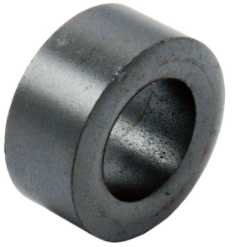
If you were to use one of the above ferrites to make an HF balun for an HF transmitter, then they will be ok for up to about 2 watts or so (including a generous safety margin). They are 10mm diameter and have a 5mm diameter hole. They are also 5mm thick. Clearly there is not much ferrite in them, about 1.5g.
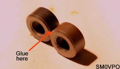
Take two ferrite rings and glue them together, side-by-side, so they look like a pair of spectacles for mice (and gerbils). If you push a wire through one hole, and then thread it back again through the second hole, then you have got two turns, and twice the power-handling capacity.
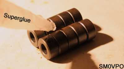
Now let us take this a step further: Take, for example, 10 ferrite rings and glue them together, 5 plus 5, to form two tubes. Now glue the two tubes side-by-side (as above) so that you have what looks like a pair of binoculars for mice (or gerbils). The resultant double-tube will handle typically 20 Watts.
Incidentally, commercial RF transformers use ferrite tubes, side-by-side, with a bit of copper tube stuffed through the holes used as the 1+1 turn primary (low impedance) winding from the RF power transistors. 3/16" (4.76mm) outside diameter copper brake pipe will fit into these ferrites, and you can wind the output secondary winding through the holes in the copper tubes.
A few years ago I needed to make one of these output transformers, but I didn't have any copper tube to hand. So I cut some braided coaxial cable and removed the outer insulation. I then carefully pulled out the center-conductor and pushed a short length of plastic tube in there. This I pushed through the ferrite rings, and I could add my secondary winding through the plastic tubes. The advantage of braid is that you can stretch or push it a bit, to get a smaller or larger diameter, to fill the holes in the ferrite. It was quite fiddly, but it did the trick. The coax braid is the transformer primary.
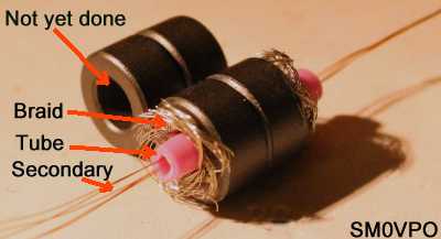

The example above shows how it was built, but my plastic tube had thinner walls. The tube also melted when I soldered, but that doesn't matter because the secondary winding is insulated with enamel. You can use paper drinking straws from Burger King.
The quick'n-simple method of calculating coils given above works for all coils on any one specific former. An air-cored coil using a former with a fixed length will normally have a fixed coil length, so the ROT works for them.
My basic (very [very] approximate) Rule Of Thumb for "guestimating" air-cored coil values is to take the frequency, work out the wavelength, then express the wavelength as number of turns and capacitor value in pf. For example, 5MHz: Wavelength is 300m / 5MHz = 60 metres. To make a resonant tuned circuit you use a coil of 6mm diameter, 6mm long (pile-wound), 60 turns and 60pf. Again this is not exact, but it will get you in the right area. The impedance will be somewhere around 500Ω-ish in the HF spectrum.
This ROT is almost exact at 5MHz, but in the range of 500kHz to 30MHz the errors start to creep in towards the band edges. If you have a coil and a preset capacitor then this is not normally a problem. So let us refine this a little bit:
The standard formula for frequency, inductance (L) and capacitance (C) uses the divisor ²√LC. So if you use 5MHz as the referance frequency, then you can multiply or divide the turns and capacitance by ²√ of the frequency ratio.
Example: Say you want 50MHz. 50 is 10X greater than 5MHz reference frequency (Frequency ratio = 10:1). ²√10 = 3. Divide the number of turns and pf by 3. So 5MHz = 60pf and 60 turns. 60/3 = 20. You need 20pf and 20 turns for 50MHz.
Remember also that a pile-wound coil requires fewer turns than a single-layer coil. So if your "guestimate" results in a coil length of less than 6mm then for the single-layer coil you must add something like 30% of the number of turns.
Once more it sounds very complicated, but in reality it is easy:
If you want a different impedance, eg 1000Ω, then increase the coil and decrease the capacitance by the same proportion.
If you want to get it really accurate the first time, or if you want the values more exact, then look at my Radio Calculators page. The object of this section is to roughly estimate in 30 seconds, eleminating the need to go do any research. You can often build a simple test oscillator in less time than it takes to calculate the coils.
In this article I have tried to pass over a general "feel" for ferrites, coils and capacitors, without the need to constantly refer to formulas. The resultant values are approximate for air-coils and caps, but the object is to get you in the correct general area (without using a big stick 😉).
For ferrites rings, a good evaluation will give surprisingly accurate results and the results are good enough for most RF filter designs. You also have a rough guide for power handling, and a good idea about coupling transformers and baluns.
I hope that this information has given you some "food for thought". You can always e-mail me at harry.lythall@[my domain].com, although I would prefer that you visit my messageboard if you have any questions about this or any other project. I always look forward to receiving feedback, both positive or negative 😊
Very best regards from Harry Lythall
SM0VPO (QRA = JO89WO), Märsta, Sweden.