
Here is the super NEW miracle improved "Frequency Modulation Wireless Microphone" (BUG) with added easablilty, readability and copyability. This was necessitated after the number of E-Mail questions posed by people who were confused by the layout of the project(s). Before proceeding with the interesting bits, please note:
This project is a miniature, VHF FM (wideband) Wireless Microphone transmitter of the type that are commonly refered to as BUG's. Note that "BUGS" are illegal but "Wide-Band Frequency Modulation Wireless Microphones" (WBFMWMs) are not, as so many people have told me (including the RSGB!). Besides, the AF sensitivity of this transmitter prevents it from being an effective bug for eaves-dropping! I personally use one of these WBFMWMs plugged into my HF rig headphone socket so that I can "earwig" QSO's and nets when sitting on the toilet, washing the dishes, bringing in the coal, etc. I know from experience that this project can be used to stimulate interest in Radio in older children, and this was also one of the projects given to a group of scouts and girl- guides to construct. Surprisingly, I found the girls made a better job of soldering than the boys! The circuit is very simple and needs no explanation for construction although the kids needed some guidance when soldering.
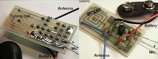
The coil version uses a 1/4" (4mm) diameter coil wound on a drill bit, although the PCB version has the coil fabricated on the PCB itself. A simple piece of insulated wire about 60 cm (2 feet) was fine for the antenna, and is connected to a 1-turn tapping of the coil. Use tinned copper wire for the tuning coil and not the enamelled wire for kids to build. It is much easier for them to solder the antenna, without "mashing-up" the coil, whilst trying to remove the enamel. The PCB version is ideal for the kits as there is no coil to wind, see the photographs on this page.
NOTE:
Since the antenna is coupled directly to the tuned circuit coil,
the final frequency of the oscillator will vary if the antenna or
the battery is touched. This could make this little circuit seem
unstable. This is a normal feature of this type of circuit. To
avoid this you will need to add an antenna buffer/amplifer but
this only adds to the complexity - not exactly ideal for beginners.
See my FM wireless microphone V5 if you need
a more stable circuit.
If you wish to use the BUG (sorry!) FM Wireless Microphone from the headphone socket of an HF rig, then delete the 4K7 resistor (and reverse the 1uf capacitor). The circuit shown is for an "Electret" condenser microphone. The transmitter may be received by any VHF FM radio, but the pocket radio I use about the house was free with WEETABIX box-tops a few years ago. The unit should have a range of at least 100 meters (250 feet) but increase the "220 ohm" emitter resistor to 1K to reduce the range (if you think that little Johnny could plant it in you and your wife's bedroom). Here is a table to give you an idea of the performance of the BUG (sorry! for get I said that!) FM Wireless Microphone Transmitter:
| Emitter Resistor | Supply current | Range (approx) |
|---|---|---|
| 100R | 30 mA | 500metres |
| 220R | 11 mA | 120metres |
| 330R | 8 mA | 100metres |
| 1K0 | 5 mA | 50metres |
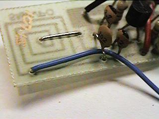
For those who would like to see what a finished microphone lookes like, here is one ready built. Note that there is no pad for the microphone, the wires are to be fitted accross the 1n0 capacitor.
The 4K7 resistor feeds the Electret condenser microphone with DC and the internal FET amplifer will develop an AF signal accross this resistor. I originally used a 47K resistor here. It worked fine but many electret microphones require up to 1mA to operate. Reducing the value to 4K7 increases the microphone sensitivity quite a lot. If you want to use a dynamic microphone then you may omit this resistor completely although it will do no harm to leave it in circuit. Please note that the audio sensitivity of the microphone is not fantastic - i.e. you cannot use it to bug a room. It is intended for you to speak directly into the microphone as you would with any other normal microphone. Do NOT expect to hear a whisper at 5 meters (15 feet) because you won't.
The microphone sensitivity is quite low. This is normal for this type of circuit not incorporating a microphone amplifer. A high-output type microphone is therefore required. If you need a microphone amplifer then see my FM wireless microphone V5 for a suitable circuit.
Now we come to the crunch. Everyone wants 5Km range and 100% stability!
Well you know how the old saying goes?
With the original values shown the output power and stability are at the best compromise for a normal domestic FM radio receiver with an AFC function. If the transmitter battery connections are in close contact with some form of ground-plane, chassis (telephone line?) or a long microphone cable then stability will become excellent. If the unit is hand-held then it may become almost unuseable. Adding an extra antenna wire connected to the one of the battery tracks on the PCB will improve this considerably.
No difficulty should be experienced by anyone, but if you are using components that are at hand in the junk box, then all resistors may vary from minus 50% to +200%. All capacitors used for coupling and decoupling may be anything from 470p to 100u. The 1n0 accross the microphone may be anything from 270p to 2n2, if it is too large then the modulation will lack the higher treble frequencies. With the component values given, the BUG (sorry!!) Wireless Microphone will operate at about 106MHz. Increasing the tuning capacitor 12p (6.8p) will lower the frequency.
With the PCB version you will have no difficulty finding the BUG (sorry!!) Wireless Microphone carrier frequency on a domestic FM radio set, it will be at about 106MHz. If, however, you cannot find the carrier then:
Incidentally, this little .. er! .. transmitter, works well on 10 meters FM with a lower (and quite acceptable) deviation. The coil is 14 turns with a ferrite slug (tuning) and the tuning and feedback capacitors increased by a factor of 3. Take care with the positioning of the tuning coil, as this will alter the frequency. It should not be possible for a user to touch the coil. In the FM version this is of no consequence. This unit can also be used toan electric guitar and your FM radio/stereo becomes a guitar amplifier!
Have fun, de HARRY.
Return to INFO page