
My FM Wireless Microphone has been a very popular project with beginners and experienced constructors alike. It has been used inside guitars and as the basis of a remote control system. I do however, receive many requests for a higher powered circuit and better microphone sensitivity. Now I can introduce the new FM Wireless Microphone (v5), which also has a better frequency stability, over 1Km range (under ideal conditions) and is good on microphone sensitivity. This has been achieved by adding an RF amplifier buffer (with 10dB gain) and an AF preamplifier to boost the modulation a little.
Construction is quite simple. L1 is 3.25 turns in spiral form and is an integral part of the PCB foil pattern. The two BC547 transistors can be replaced with (almost) any small-signal NPN transistor, such as the 2N2222. The final stage is a BC557 PNP general purpose device. If you use different devices then you should select the 1M0 resistor for 5-volts DC at the collector of the the first transistor. Select the 47K resistor for 3 - 4 volts on the collector of the third transistor. Here is the V5 component overlay drawing. Note that there is a modification:
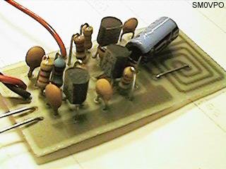
There used to be a 1n0 5mm cap for supply decoupling, but after a cange of component supplier (manufacturer?) there developed some form of RF instability when the gain of the PA transistor was a little above normal. Replacing the 1n0 to an electrolytic capacitor of 22uf cured this problem totally. Any "radial" (the leads both come out of the same end) type electrolytic capacitor from 0.47uf upwards cures the problem. The finished unit draws about 30mA which should vary as you touch the tuned circuit, a good test that the unit is oscillating. You should remove the 4K7 resistor if you use a dynamic microphone.
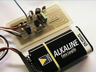
The PCB is 50mm x 25mm, a little larger than the first version but there are three stages instead of just the one. The first prototype is shown above, beside the battery powering it. The output power is about +10dBm which is about 10dB more than the first FM Wireless Microphone. This would theoretically give it 3.12 times the range (1.6Km) but I have only tested it using a handheld receiver with the TX laying on the bench indoors. But I got a comfortable 700 meters (and a few funny looks from our neighbours).
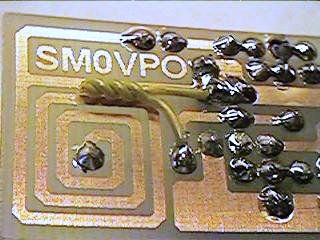
Above you can see the addition of a "gimmick" capacitor added across the 12p tuning capacitor to lower the frequency of the transmitter. Make the capacitor by twisting two lengths of single core insulated hook-up wire, about 2cm long. This will reduce the frequency to the bottom end of the band. Cut short the capacitor to increase the frequency to the desired final frequency. If you cut it a few KHz too high then just twist the gimmick a little tighter.
The PCB foil pattern and layout will be placed in the download section of my homepages. Have fun and please be aware that the higher power of this project may render it ILLEGAL in your own country. I can accept no responsibility and it is up to you to check that you may legally use it. I will accept NO complaints from any country/state correctional facility.
Very best regards from Harry Lythall