
This year I have been doing a LOT of work with NiMH, Li-Ion and LiPo cells, together with Arduino projects. I even needed to charge a 4-Volt VRLA (Valve Regulated Lead Acid) battery for my RC boat. My bench PSU (Power Supply Unit) has been in almost constant use, and I really needed to get myself another one. I came up with a design and priced the components at about SEK300 (US$25), which of course comes with the hassle of laying out a PCB (Printed Circuit Board), etching, drilling, and sourcing components.
I was recently on temu.com (a China-based site with many sellers) and saw a bench PSU kit advertised for just SEK74 (US$5.50). I cannot even buy the components for that price. The kit description promised 0–30V at 0–3 Amperes. The picture on the website showed a double-sided PCB with components, three Op-Amps, and potentiometers. I was impressed, so I bought a kit. This page documents my experiences and how I got it working as I wanted.
This "review" has almost become a new project. Although the basic kit has it's faults, it can become a really cool, quitet, stable and useful bench Power Supply Unit (PSU) for lower power requirements. Like most PSU projects, dissipating heat is vital, so I have concentrated a lot on the choice and construction of the heatsink.
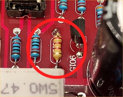
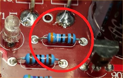
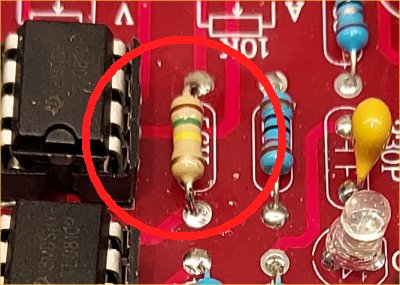
I thought that the board was really professionally made — pre-tinned, solder-mask, silk-screen printed, the works. All the resistors were E48, 250mW components with five colour bands. The holes are plated-through and clearly marked with component values, which made assembly easy. A little tip here: when fitting resistors, identify them AND check them with a multimeter. If, like me, you are used to E24 series with four colour bands, then it is easy to make a mistake, but it does no harm to read AND measure before soldering in the components: The only people who do not make mistakes are those people who do not do anything. I used E24 resistors for the modifications listed in this article.
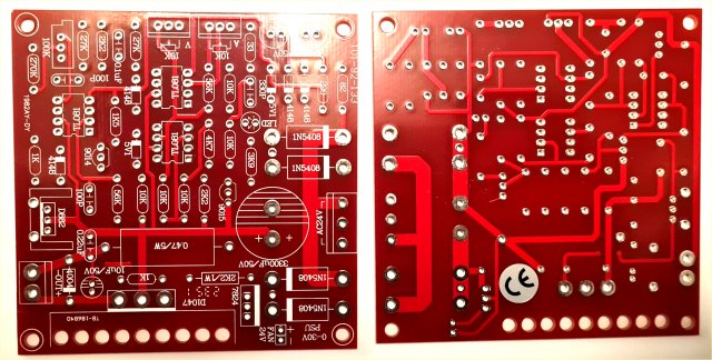
Unfortunately, there was no circuit diagram or assembly instruction, but it is quite clear to see where everything is located. The PCB lists the component values; NOT the circuit designation. The Voltage and Current potentiometers were supplied without mounting nuts, and there was no data for the colour-coded wires to the potentiometers. There was a 100KΩ resistor with no place on the board, and the 2.2KΩ resistor (R19) was missing. Other than that, all went well. The through-plated holes are quite large so they can be soldered from either side of the board, which makes life easier for me and for the modifications I made.
The kit needs a 24-Volt AC transformer, or a 12V-0-12V transformer (not supplied). Fortunately, I already had one at home, but rated at only 1.5 Amperes — more than adequate for my needs. Assembly went very well, but you do need to think a little before soldering, for example VT2 (D822) must be mounted on the supplied heat-sink before soldering. Once everything was assembled, it was time to test it.
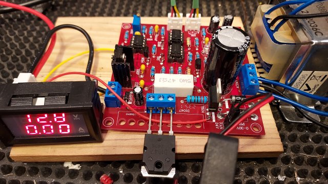
You must bear in mind that any power project, whether amplifiers or power units, must be checked carefully before applying power. For initial testing, I put a 12-Volt, 100mA lamp in series with the power connections to the board, initially using 30V DC from my main PSU. No smoke, no sparks, and the unit only took a few milli-Amperes. The board requires AC in order to create a +35V DC power source, and also a -5V supply so the operational amplifier used for current limiting can operate down to 0V on the input pins. With no smoke, no crackling, and only a low current, I connected the 24-Volt transformer.
The unit worked first time, or at least I could vary the voltage from 0V to 27.5V (I suppose this is a Chinese 30 Volts?). I also saw that the “Current Limiter” lamp was permanently lit, but the regulator had NOT shut down, so current limiting had NOT kicked in. Resistor R22 (3.9KΩ) was also getting quite hot (True fact: the threshold of pain for men is 60°C [140°F], but 62°C for women). The problems to fix are:
I am using a plastic enclosure, so heat is a greater issue for me. Since I only want this PSU for charging NiCAD, LiPO and Li-ion cells, I do not normally need more than 600mA, but it can be good to have up to 1.5 Amperes maximum. The ventilated enclosure material is an important consideration when dimensioning heat-sinks. As a general rule of thumb:
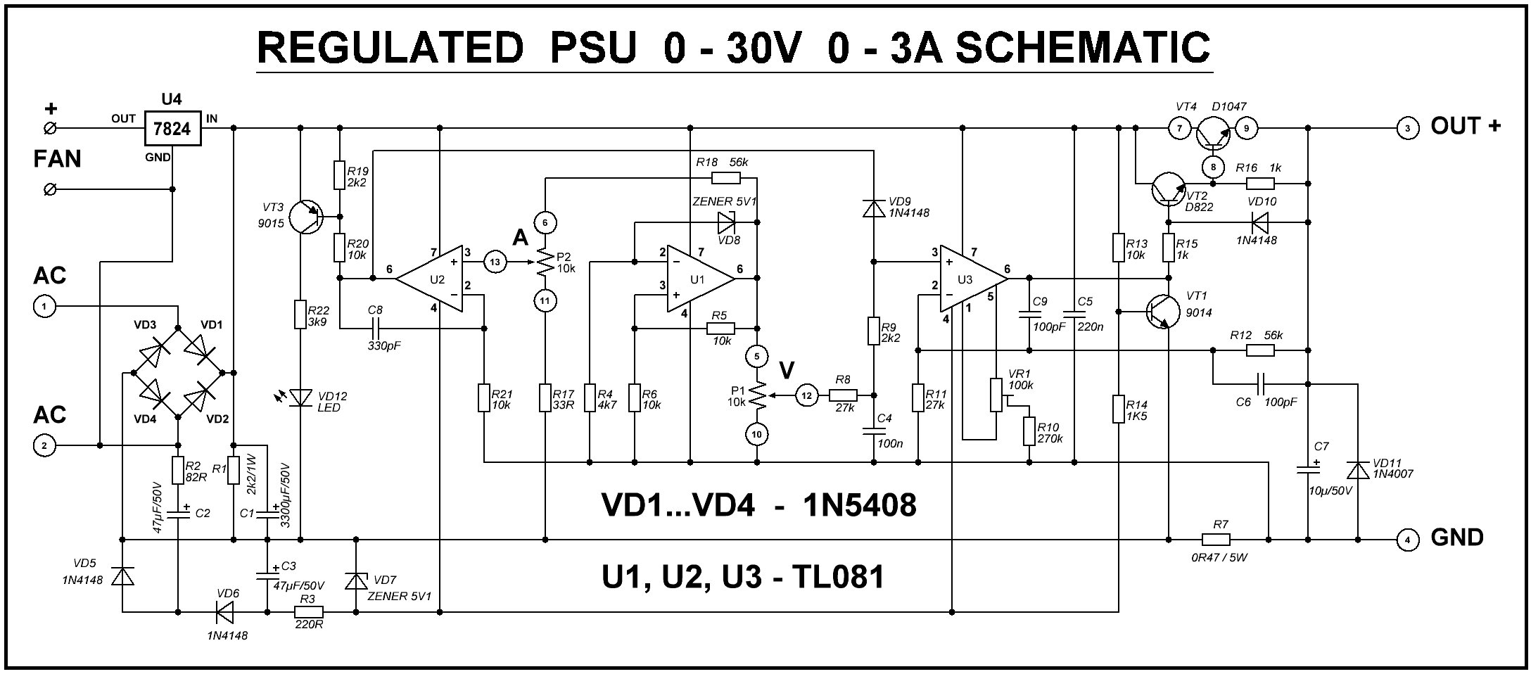
This is easy. My 24-Volt AC transformer (12V-0-12V) actually delivers 26V RMS (Root mean Square). After rectification (26 x 1.414 = 36.8V) and the 1.4V drop of the rectifier diodes, the board DC supply rail is 35V. The TL081 (U2) output (pin 6) will not go higher than about 30V. After the power Darlington regulator, only about 27.5V remains — exactly what I was seeing. I have just found out that the voltage can be increased to 30V by changing R12 (56KΩ) to 61KΩ (56KΩ in series with 4.7KΩ). I’m not bothered about the full 30V; 27.5V is good enough for me.
I am still risking the TL081 until I get a new delivery of OpAmps. It seems to work ok, but this is why I am a little concerned:
I am concerned about the maximum voltage rating of components. The TL081 is rated at ±18 Volts (36V), and this PSU already has 35V + 5V = 40V power to the OpAmps, which has exceeded the maximum allowed voltage. I strongly recommend that you replace the three ICs with something like the OPA551 ±30 V (60 V total). This rating gives all the headroom you could ever need, and the high differential input limit means it won’t complain if one input wanders off while the other’s still catching up — something that can absolutely toast a TL081 in the same situation. Other alternatives can be:
| OPA551 | Rated up to ±30 V (60 V total).
Gives a good safety margin. Good choice if you want the smallest change in supply rating while staying safe. |
|---|---|
| OPA452 | Rated up to ±40 V (80 V total).
Gives a good safety margin. Also a good choice. |
| OPA453 | Rated up to ±40 V (80 V total).
Also gives a good safety margin. Good choice if you want the smallest change in supply rating while staying safe. |
| OPA445 | Rated up to ±45 V (90 V total).
That gives a better safety margin. |
| OPA454 | Rated up to 120 V total.
Maybe a bit of overkill, but does give a very good safety margin. |
I checked thoroughly but there was no wiring error. When repairing equipment, you know it has previously worked, but with new builds, you must look closely, for example, incorrect component fitted. The Operational Amplifier U2 output (pin 6) cannot go higher than 30V (C8 is noise rejection). Since U2 operates with about 0V on both inputs (pins 2 and 3), there is also a little 100Hz ripple at the output. So there’s a 5V (plus noise) difference across R19 and R20 without current limiting engaging — enough to turn ON VT3 and light the LED. A small design error.
The solution is to replace R19 (2K2Ω) with 680Ω, OR replace R20 (10KΩ) with 33KΩ. I simply soldered a 1KΩ resistor across R19 — I'm lazy, but effective. The LED now stays OFF unless U2 pin 6 falls below 15V.
R22 gets hot because it dissipates 230mW, close to its 250mW rating — too close for comfort. Such projects may be left powered for hours, days, or even years, so “slow cooking” is possible. Change R22 from 3.9KΩ to 6.8KΩ (ideally 1W) and leave it 5mm above the PCB.
R22 drives current through the Current Limiting LED, and brightness is not a critical spec. I prefer a softer red LED instead of the blinding blue one supplied. Remove the LED from the board and fit a 2-pin header so you can mount the indicator lamp on the front panel in a proper holder. in the assembled version I also added a green LED to indicate when the PSU is ON. Don’t use DC to drive the power LED — short the LED with a 1N4148 diode so it conducts both ways, and use a 470nF non-electrolytic capacitor from the transformer’s AC output. Capacitors don’t dissipate power, so they stay cool — far better than wasting another ¼ watt for an LED.
Current Limiting
As supplied, the unit will deliver 3A, but that needs a large heatsink, a fan, and good ventilation. VT4 can dissipate over 105W (35V × 3A). I’ll never use 3A for charging batteries, and my transformer is rated at only 1.5A (50W max). Also, the current limiter potentiometer adjusts 0–3A with only about 180° of rotation — very touchy! Increasing R18 (56KΩ) to 82KΩ spreads the current 3A range across the full 300° of rotation. Although 82KΩ worked for 3A, I restricted mine to 1.5A because I have a light plastic enclosure. To set the PSU maximum current limit:
| R18 Selection | ||
|---|---|---|
| R18 Value | Current Range | VT4 Power |
| 82KΩ | 0 to 3A | 105 Watts |
| 100KΩ | 0 to 2A | 65 Watts |
| 150KΩ | 0 to 1.5A | 50 Watts |
| 220KΩ | 0 to 1A | 30 Watts |
| 330KΩ | 0 to 600mA | 20 Watts |
I have included the power dissipation (heat) worst-case scenario for the different output current options. This will affect the heatsink size you will need for the 2SD1047 (VT4) regulator transistor.
Another problem is that the power reservoir capacitor is only 3300μf, which gives a 1V peak-to-peak ripple when loaded to just 1A. At 3A, you can expect about 3V ripple.
Remember that when the voltage potentiometer is wound up to more than 30V (R18 too low, or R12 too high), then the Negative FeedBack (NFB) control loop is broken. It is the NFB loop that stabilises the voltage and removes supply ripple. 3V of ripple will almost certainly appear at the output if you screw the voltage up to over 30V output. You can reduce R12 to maintain NFB and eliminate ripple, but this also reduces the maximum voltage available. I don’t mind some ripple at 30V since this PSU will mostly charge batteries.
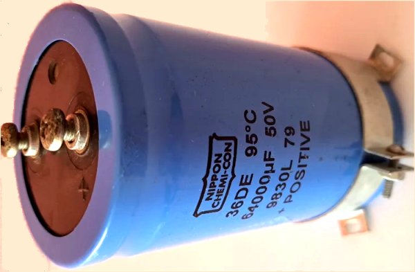
The solution is to connect an external 64,000μF capacitor in parallel with the 3300μF, mounted in the PSU case beside the board. Problem solved.
Heat removal is vital and often under-engineered. I want an instrument that runs cool and can be used 24/7 under worst-case conditions.
If you use a cheap 115/230VAC to 24V transformer, it may get warm. Toroidal transformers tend to run cooler. I’ll mount mine in a nice-looking (and cheap) plastic box, so I must ensure good heat removal. My transformer only gets slightly warm, but I’ll mount it on an aluminium panel that can attach to the cabinet’s posts — no problem.
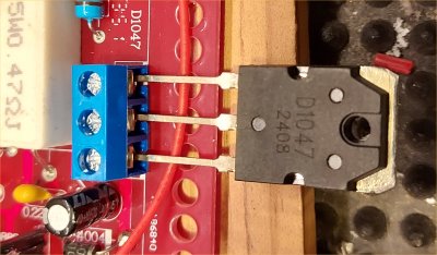
The 2SD1047 (VT4) is the main heat generator. Nothing in the kit specifies heatsink size. Here you need to decide how hot heatsink can be allowed to become. This will be determined by your cabinet for the finished PSU. For example:
1 - Metal box - 100°C maximum - room temperature is 20°C - you can afford 80°C temp rise
2 - Plastic box - 50°C maximum - room temperature is 20°C - you can afford 30°C temp rise
The power dissipation of VT4 is likely to be:
1 - PSU delivers 3A maximum - VT4 dissipates 105 Watts of heatNow you know the temperature rise allowed and the power you need to dissipate, then you can work out how many degrees per watt you should dimension your heatsink.
Worked Example #1: 1.5 Amperes - convection cooled
| Formula: | Degrees °C/W = 50 / √(Area cm²) |
For 0.4°C/W, you need 15,625 cm² of exposed metal, or about 90cm x 90cm (2 sides) = total area. The heatsink would therefore need to be two plates 15cm x 10cm (with 2 sides) = 300cm² per vane. The bad news is that to achieve 15000 cm² you would need 50 vanes.
This is clearly not practical, so you cannot use a plastic enclosure with convection cooling. You would therefore need to have a metal case and degrade the heatsink so that you need fewer vanes. A 12 Volt 1 Watt computer fan can also be added to the heatsink. This will allow the heatsink to dissipate 3x the heat, so calculate for 1.3°C per watt.
See the section Reducing heatsink Size below.
Worked Example #2: 0.6 Amperes - fan cooled
Assuming a 20°C allowable temperature rise and 20W VT4 heat dissipation at 0.6 Amperes, the heatsink must have better than 20°C/20W = 1°C per Watt performance. This, however, is a very mild case. Use the same formula for convection cooling (heatsink mounted outside the enclosure and the vanes are vertical) BUT a 12 Volt 1 Watt computer fan is added to the heatsink. This will allow the heatsink to dissipate 3x the heat, so calculate for 3°C per watt.
For 3°C/W, you only need 277 cm² of exposed metal, or about 6cm × 4cm - double sided = 48cm² per vane. 6 vanes will give you 300cm². This is practical for my plastic enclosure: Three sheets of metal, sandwiched and folded at the sides. The bottom sheet can form a 6cm x 4cm x 4cm tube, which fits a computer fan perfectly.
The second kit I built for myself only gives 650mA, more than enough for charging cells. The heaviest dissipation is when the PSU output is a dead-short, and with the above heatsink and fan, the maximum temperature is 42°C, so it is a little over-engineered. When this project is published, I will add thermistors to the heatsink and transformer, to drive the fan only when the fan is needed.
For the 1.5 Ampere version, a practical heavy heatsink (low °C / Watt) might be a 6 × 6 × 12 cm square copper tube with 20 internal fins and a fan at one end. This gives ~17,280 cm² area (≈0.38°C/W). This is still large. The fan should suck air along the fins and out of the box, not blow warm air in.
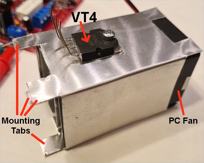
The picture above is my home-made heatsink, 6cm x 4cm x 4cm with 4 internal vanes, using 0.7mm thick aluminium sheet. 1.1°C/watt (measured) with 1-Watt fan. The 8 tabs are to be folded outwards for mounting on the back panel; the back panel supports both fan and heatsink. The fan is mounted outside the enclosure. I made mounting tabs at both ends of the tube, but they are only needed at one end and will be cut off when I assemble the PSU in the enclosure. Thermal paste is fitted under the VT4 and between the internal vanes (2 sheets of metal).
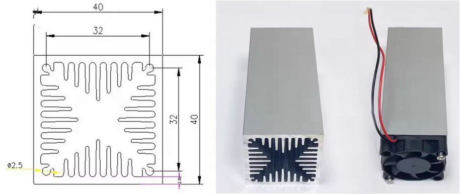
The advantage of the tube-type heatsink is that it can be mounted INSIDE the equipment enclosure, air is blown through the tube and out of a hole in the back panel. This keeps the inside of the enclosure cool and avoids having a live heatsink on the outside with 35 Volts DC on it. You must, of course, add a few holes in the enclosure to allow cool air to enter. If you make the holes close to the transformer then even the transformer will run cool.
If the heat-sink size is a problem for you, then you can mount the PSU in a metal box and run the heatsink at a higher temperature (up to 60°C, for example), which would halve the heatsink size. Instead of a 1-Watt fan, you could use a 10-Watt fan and again reduce the heatsink size proportionally (check the air-flow spec), but the instrument could become noisy.
Whatever you do, remember that the transistor will still generate the same amount of heat, no-matter how you handle it. If you want a more detailed explanation then I have a complete article about heat-sink calculation at Heatsinks: https://sm0vpo.com/begin/heat-1.htm.
One interesting anecdote here, I have seen commercial power units where the heat-sink was inadequate for "worst-case" scenarios. The PSU worked perfectly, until maximum current at low voltage was demanded. The heatsink became too hot and a temperature sensor circuit shut down the power unit, displaying a "Temperature overload" error. This makes it YOUR fault, and not the designer's fault.
I did NOT solder the 2SD1047 to the PCB as intended — the kit PCB didn’t allow for a large enough heatsink. Instead, I fitted a 3-pole screw terminal so I can mount the transistor directly on the heatsink, wherever I like. The fan (12V, 70mA [1-Watt]) will blow cool air through the vanes. Add a 68Ω, 1W resistor in series to run it quietly from the 24V fan outlet on the PCB.
I could have mounted the heatsink on the rear panel, but then it would be live at 35V unless insulated. Mounting it inside makes it safer and improves thermal conduction.
NOTE 1: I could NOT find any heat-sink calculation online, so I measured it myself using a power resistor and thermometer. My formula matches commercial data closely.
NOTE 2: If you mount this project in a metal box, you’ll need a smaller heatsink, but the box itself will get warmer.
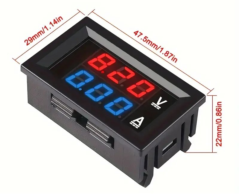
My front panel uses a cheap (US$3) digital volt/amp meter from Temu, two binding posts for PSU output, and the two adjustment potentiometers. I replaced the 10KΩ current limit pot with a logarithmic taper for finer low-current control (0–500mA). The last 30% of rotation then covers 0.5–1.5A.
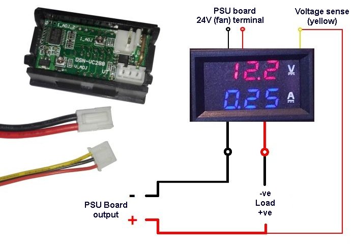
NOTE 1 - The meter power leads are connected to the fan terminal post to get 24V power for the meter. Try connecting ONLY the red wire, but leave the black wire disconnected. With some units the black meter power wire is connected to the load negative terminal, which will cause an incorrect reading (test resistor shorted). If it works then leave it off, otherwise connect it.
NOTE 2 - The thick RED wire from the meter module IS the load minus (negative) terminal, this is NOT a mistake.
Since this project uses 115 / 230 VAC input, it is not suitable for children without supervision. High voltages are potentially lethal.
I know this is outside the scope of this article, but if you want to charge cells, especially LiPO cells, using this PSU, then check the maximum terminal voltage of the cell (eg. LiPO = 4.2 Volts). Set the PSU voltage and maximum current BEFORE you connect the PSU charger to the cell.
1 - Check the cell specification max voltage and current
2 - Do NOT leave cells on charge unattended
3 - Check that the cells do not become warm (a sign that someting is wrong)
4 - Cells in "series" - use a charge balancing module
There are many recorded cases of house fires and damage caused by incorrect charging of LiPO and other cells.
Although not perfect, I think this is a wonderful kit for the money, if you can accept correcting some of the faults. It didn’t quite deliver all that was promised. In my experience, kits from “the East” usually meet about 85% of their claims, so a few adjustments are to be expected. Knowing these limitations, the final result is great — well worth every penny. My total budget was about SEK120 (US$10), which gave me a PSU that would otherwise cost ten times as much. The 64000μF capacitor was "canibalized" from an old Overhead Projector that was thrown in an electronic scrap bin, but it can cost you, maybe, US$8 if you buy new.
I had thought of giving some links to the kits, but the suppliers on aliexpress.com, temu.com, fruugo.com, etsi.com and banggood.com seem to change every couple of weeks, so any links I give will be always out of date.
I really must thank Ivan (OK1SIP) who gave me valuable feedback information on the first draft of this project. His comments caused me to investigate further, add to the "corrections" information, and to simplify some of the calculations and text.
Thank you very much for visiting Harry’s Homebrew Homepages and for reading this far. I hope this review has helped you and given you some food for thought. You can e-mail me at harry.lythall@[my domain].com, or at hotmail@sm0vpo.com (not a typing error) or british.inteligence.sweden@sm0vpo.com (also not a spelling error 😉). I would prefer you visit my message board if you have any questions. I always appreciate feedback — whether positive or “constructive” 😊
Very best regards from
Harry Lythall
SM0VPO (QRA = JO89wo), Märsta, Sweden.