
In days of old, when knights were bold, and toilets we not invented ... well, a long time ago, anywaythere was a good selection of components for the home constructor. Sadly, those days are ended, when it comes to wireless. So it is back to the way we used to operate: Improvise. I need a dual-gang variable tuning capacitor having capacitances of 50pf + 50pf, and able to stand the anode of a transmitting valve (rating = over 1000vDC).
A quick search of Google gave no results. A long search of Google showed me that I do not earn enough! So I shall improvise, that is just what this project is all about. Follow my way of thinking and then devise your own custom variable tuning capacitor to suite your own specific needs. Here´s how I made mine.
The basic problem with making air-spaced capacitors is that the "rotor" (moving) blades, or vanes, must pass between stationary, or "stator" vanes, to create the capacitor. Any horisontal deviation of the plates when rotated causes the plates to short circuit. Commercial units used to suffer from the same problem as the distances were so tight, in order to reach the higher capacitances.
From a couple of basic experiments I found that 1.2mm clearance between plates can withstand 1500v DC. I also found that I get approximately 1pf for every pair of 1cm square plates that are placed 1.2mm apart. In my experiments I used copper-clad board off-cuts to do the experimenting. Then I thought "why not make a PCB capacitor?".
You can easily etch the stator vanes, with the desired shape, onto a single-sided copper-clad board. If several boards are stacked into a pile, and alternate boards connected to each other, then you build a capacitor. All that is needed is to move one into the other. Easy - peasy!
Copper-clad boards are quite robust things, especially if you sandwich them, or bolt them together. The copper can be soldered, or used to make connections to bolts. Copper can be etched to simply support, without making any electrical connection. This can also be used to support a spindle.
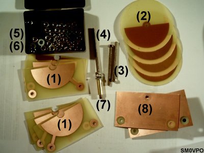
Instead of words, here is a picture of the materials, followed by a picking list.
My nuts are 2.5mm thick, and if you examine the pictures you can see how many nuts you need for any given number of vanes. In my example, with one stator and one rotor plate, I worked out that a copper semi-circle 6cm Diameter (3cm radius) has 0.5 x 3.141 x 3cm x3cm = 13 square centimetres surface area. That is 13pf. With two stators and one rotor I would have two capacitors: both halves of the rotor plate are used.
| 14 square centimeters area per vane | ||
|---|---|---|
| Qty of Stators | Qty of Rotors | Max. Capacitance |
| 1 | 1 | 13pf |
| 1 | 2 | 26pf |
| 2 | 1 | 26pf |
| 2 | 2 | 39pf |
| 2 | 3 | 52pf |
| 3 | 2 | 52pf |
| 3 | 3 | 65pf |
| 3 | 4 | 78pf |
| 4 | 3 | 78pf |
| 4 | 4 | 91pf |
| 4 | 5 | 104pf |
| 5 | 4 | 104pf |
| 5 | 5 | 117pf |
| 5 | 6 | 130pf |
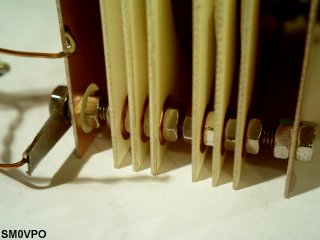
It is important that you work out the TOTAL length of the support rods (3) before you cut them. For three stators there are 4 nuts, plus three PCB thicknesses, two end-plates with another three nuts, and three short spaces, ca: 5mm. The drive shaft is the same, plus extra for fixing the control knob.
From the table you can see that I need three stator plates and two rotor plates for each capacitor, to get 50pf. As regards alignment, if all the single.sided PCBs are facing the same direction there is no possibility of short circuits, even if the mechanical alignment is bad. Mine was good.
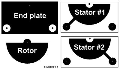
I shall add the artwork for these file to my download site later. But the boards all look like this. The end-plates and stator vanes must have the holes aligned perfectly, so drill with a 1mm pilot hole, then enlarge to 4mm. The holes in the center of the stator plates must be enlarged to 10mm Diameter BEFORE the board is cut to size. This is to allow the drive shaft to be fitted with nuts. The drive shaft is supported ONLY by the end-plates.
The artworks I have provided are for my own two-gang capacitor, therefore there are two different shapes for the stataor plates. There is no reason why you cannot add a third, or even a fourth support bolt and have a three, or four-gang tuning capacitor.
As you can see, the artwork is simple, but there is no reason why you cannot paint them on copper-clad boards with an etch-resist pen. But I suggest you use a bit of Veroboard as a guide to pre-drill the 1mm holes. Use a compass to mark the circles and fill in with nail varnish, or an etch-resist pen.
You may wish to use 1mm thickness boards for the end-plates. I used 0.6mm and found them to be a little flimsy, but usable. If your capacitor is for SSB, regenerative receiver tuning, or some other application requiring good stability, then you should make the end plates out of aluminium, or bolt aluminium to the end plates. This is practical as the aluminium can also form a bracket to bolt the capacitor assembly to a chassis.
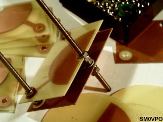
I found that the assembly order is quite important. Position and fit ALL 4mm threaded support rods, and the drive shaft to one end-plate. Fit nuts then add the stator plate, rotor, stator, rotor, stator, bolting them as you go. Make certain that the rotor plates are all aligned and properly tightened as you go along. Use a ruler to measure the distance between the first end-plate and each stator-plate at BOTH sides. They should all be parallel.
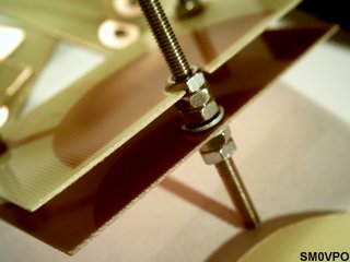
Not that washers fitted to the drive shaft have two sides, one smooth and one rough. The smooth side must be in contact with the end-plate copper, and the split-washer is fitted at the other side. You only need gentle pressure. If you want a better contact then you can tin the copper with a nice even layer of solder.
After the first capacitor has been added then you leave a couple of nillimetres space and continue with the next. Again, ensure the first stator vane is parallel with the first end-plate. Also be sure that you are now using only right-hand vanes. All the left-hand vanes should have been used for the first capacitor. Fit nuts then add the rotor plate, stator, rotor, stator, bolting them as you go.
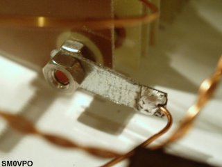
When the rear end-plate has been fitted, there should be a few millimetres of threaded rod for you to make connections to the capacitors. Each of the two rods connects to only one capacitor. The connection is made using a solder tag. My solder tag is home-made, mainly because I do not know how to ask for them in Swedish.
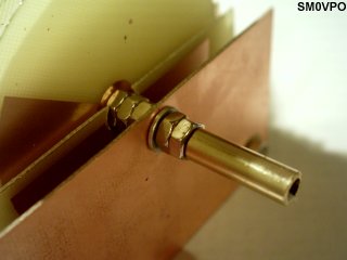
Now that the capacitor has been assembled, you need to make it compatable with 1/4" (6mm) knobs and things. Shove a short length of 6mm brass tube over the end of the shaft. If the drive shaft is solderable, then you can use a heavy iron and melt a little solder in the end of the tube. But if your threaded rods are made of stainless stell, then you need to add a drop of super-glue or epoxy cement down the end.
When the unit is assembled, check that the drive shaft rotates freely, but without any "play" (glapp). Check that the end-plates are not shorted to either of the support rods, and inspect well to make sure that only the first capacitor stator vanes are connect to one rod, and the second to the other rod.
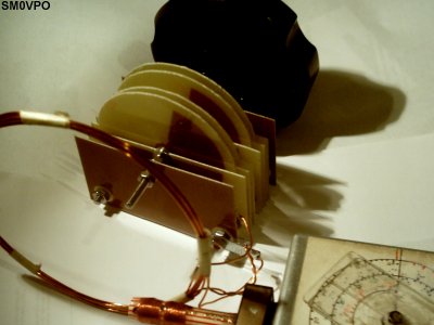
If you add a nice large tuning know then the capacitor feels nice and smooth. If you want that really nice "polished" feel to it then the ball-races for skateboard wheels can be used as the shaft bearings.
Finally, use the Grid Dip OScillator (GDO) and a coil of wire to check the maximum/minimum capacitances. The first prototype has a capacitance range of 5:1, but if you lengthen the whole unit to have a wider space between capacitors and end-plates then the maximum/minimum can be extended to 10:1. If you want no interraction between the capacitors then add another end-plate between the two capacitors. It is all quite simple, and just a matter of thought.
A fixed capacitor across the temporary coil should give the same frequency as the tuning capacitors calculated capacitance.
Another little idea, if you need to have an alignment "padder" capacitor in your circuit, then you can even make the rear end-plate a bit more complicated and fit other components to it. After all, it IS a pronted circuit board :-). Another idea is to change the artwork so you can make "butterfly capacitors" for VHF work, or even change the physical size of the unit.
Well, I have presented yet another idea, so please go ahead and experiment for yourself. I hope I have stimulated new ideas and that you will perhaps return new ideas to me and others on my messageboard.
Very best regards from Harry Lythall, SM0VPO, Sweden.
Dont forget to visit my messageboard if you have any questions about this or any other project. I always look forward to receiving feedback, positive or negative. You do not have to register to post messages.
Very best regards from Harry Lythall
SM0VPO (QRA = JO89WO), Märsta, Sweden.
EA/SM0VPO (QRA = IM86BS), Nerja, Spain.