
I have done some work with DC PSUs over the past few months but some of the designs were either complex or "basic performers". I therefore decided that it was about right to produce a bench PSU that was simple enough to be made into another kit and have a reasonable performance too. The bench PSU specification had to:
The design I came up with was almost a discrete component operation amplifier, with special attention to the zener diode voltage reference stability. This was achieved by feeding them with a constant current source. Here is the complete bench PSU circuit diagram:
TR1 provides a constant current to a bank of three zener diodes, thus maintaining a constant voltage independant of supply voltage variations. The resistor Rx is used to sense the PSU output current and to switches off the current to the zener diodes should the output current become excessive. The 1M0 (logarithmic taper) pot causes the current sensor (TR2) to "kick-in early", so providing a variable current threshold limit. The value of RX should be (0.7/Amperes) ohms, where Amperes is the maximum output of the bench PSU. The prototype was set to 1-ampere, so Rx should be 0.5 / 1.000 = 0.5 ohms. The resistor should be rated at 1-watt, or 2x 1R0 500mW resistors in parallel for 1-ampere maximum output. I have used 4x 1R0 ohms in parallel (0.25 ohms) and have achieved 2-amperes (with a bigger heatsink).
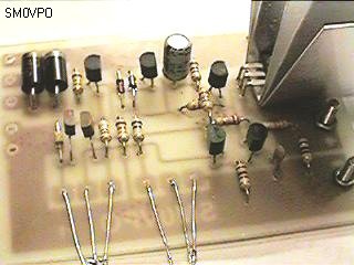
The reference diodes provide a voltage reference of 10.7-volts with tappings at 4.7-volts and 7.7-volts. The 7.7-volt tapping is used as the reference voltage. In this way we have a 6-volt swing selected by the 50K voltage pot, above and below the 7.7-volt reference. This voltage swing is amplified by the operational amplifer formed by TR3, TR4, TR5 and TR6. The DC output of the Op-Amp is arranged to give a voltage gain of a little over 2, so the 4.7-volts to 10.7-volts reference will become 0 to 15.4-volts at the output. I had thought about using PCB mounting pots, but the finished PCB is quite large and the heatsink must be quite substantial (see below). Here is the finished PSU PCB. I must emphasise that this is a prototype and not the final PCB which is much better in the layout.
A full-wave rectifier provides the 18-volts input from a 15-0-15 volt mains input transformer. The diodes 1N5401 are rated at 3-amperes. At first sight, it would appear that 1-Ampere diodes, such as 1N4001, would suffice, but this is not the case. Althought the averge current through these diodes is alittle over 500mA, the 2700uf input capacitor will be charged with short pulses, each considerably higher than 500mA. If the 2700uf capacitor were to be increased in value, then the rectifier diodes may need to be rated even higher. I used two parallel 47000uf in the prototype PSU, mainly because I wanted more output current so an additional regulator transistor is to be added. By the way, the supply smooting capacitors are not mounted on the board.Note that the TIP31 output transistor MUST be fitted with a heatsink.With minimum output voltage (say, 0.1vDC) and an 18.1v pre-regulator voltage, the TR6 TIP31 output transistor will be dissipating 18v x 1A = 18 watts. If we allow the device temperature to rise TO 120°C then we can allow an increase of 90°C over the ambient room temperature. 90°C / 18watts = 5°C per watt. A heatsink of 100 square cm is therefore required. If you wish to pull more current from this PSU then you will need a larger heatsink and change the value of Rx accordingly. Up to about 3-amperes is quite possible. TR6 may also be replaced with a darlington pair power transistor (such as TIP31 + 2N3055) if you want more than 3-Amperes, more attention will be required to other parts of the circuitry, such as the rectifier and reservoir capacitor.
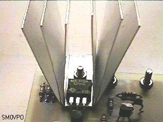
The heatsink shown above is three pieces of thin aluminium sheet, 11cm x 3cm drilled with a 3mm hole dead centre. These are bolted between the PCB and the TIP31 transistor before any other components are mounted on the board. The fins can now be bent up to form six fins, each 5cm x 3cm or a total surface area of 180cm square. This is a little bigger than the calculation, but to over-engineer is not a fault (at least, not in my opinion). Here is the completed project.
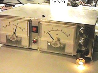
The resistor Rx can also be used as a meter shunt for the output ammeter. I have used a 1mA meter with a series resistor selected to give a true current reading. Incidentally, take off the front scale of the meters, scan them and change the scale and lettering to suit your PSU. Then you can print the scale to paper and glue it over the existing meter scale. This gives a very professional finish. If you have an unsuitable scale ammeter, then open it up and cut the shunt wire between the two poles and then you have a small milli-ameter or micro-ameter that can be re-calibrated in this project.
I am presently updating the PCB foil pattern for this project, which I will include as soon as it is complete. I may perhaps offer this project in kit form, complete with heatsink, pots and all board-mounted components, but we will see what happens.
Dont forget to visit my messageboard if you have any questions about this or any other project. I always look forward to receiving feedback, positive or negative. You do not have to register to post messages.
Very best regards from Harry Lythall
SM0VPO (QRA = JO89WO), Märsta, Sweden.
EA/SM0VPO (QRA = IM86BS), Nerja, Spain.