
Ok, I am back on the receivers again. It seems that many QRP circuits are all usually transmitters but I believe that receivers are quite important too. In this project you can build a SIMPLE receiver for VHF NBFM and the only active component is a diode. Yes, it's a crystal set! But there is a little more to it than that. This project was originally intended to be a NBFM transmitter monitor for my VHF station but one day I found that I could hear quite strong stations on it with very little effort.Here you can see the construction and one of the prototypes I built for 150 - 250 MHz:
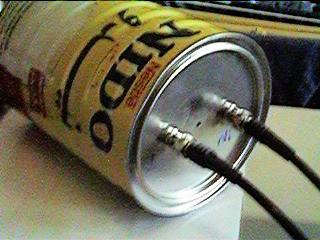
The pictures above give the mechanical construction of a cavity which may be built using household "garbage". Coffee tin's, Milk tin's or even an old galvanised dustbin have all be used sucesfully in this project. A 20dB commercial preamp in the antenna lead will increase the sensitivity, and the "shack" stereo amp forms the audio stage. Connect the output of the cavity to the PHONO input of the stereo amplifier. There is normally sufficient gain in the average stereo amplifier for this purpose. In the circuit RF is the antenna input. AF is the audio output to the stereo. D1 is a germanium signal diode, or better. I used a Hewlett Packard diode intended for UHF/Microwaves. The packet was labelled "RSCH-3486 D/C 9336" but if you can give me further information about it then send me E-Mail.
APPROXIMATE dimensions of the cavity are given below. Notice that 900 MHz is included so you can also listen to NMT (analogue celular) traffic if you live close to a base station. If you get caught, don't mention my name.
RL=Resonator length, RD=Resonator Diameter, TD=Tin Diameter, SL=Screw Length, (millimteres).
The above are given as a START for experimentation. The resonator length is quite critical and should be within +0 -10% quoted. All other dimensions may be varied by as much as +100 -50%. The input and output coupling loops may be varied. If the loop is too large then the Q will decrease. If it is too small then the output will decrease. A good compromise is 5% to 10% of the length of the resonator. I made my loops with flattened copper car brake-pipe. The prototype below used just tinned copper wire. In the left-hand loop you can see the diode inserted to make the cavity into a crystal set receiver.
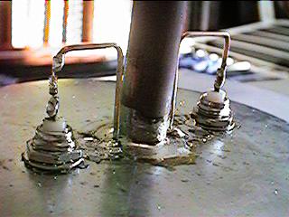
The resonator is a length of plumbing pipe cut as per the table, and soldered to the lid of the tin as shown. A screw is inserted though a nut (soldered to the base of the tin), so that it protrudes into the copper tube. The screw must NOT be allowed to touch the copper tube resonator. In my cavities I used a bit of plastic tube from a felt-tipped pen to guide the screw.
The tin may be any old coffee tin etc that has suitable dimensions and can be soldered. You can extend tins in length by using a tin-opener (back to the kitchen again !!) to remove the top of one tin and the botom of another, then solder the two (or more?) tins together to form one big tin. If you only have a 15 watt soldering iron then go back to the kitchen (yet again!) and use the gas stove to get the cavity to about 220 degrees. The 15 watt iron then works well.
I have built about twenty or thirty of these receivers for a variety of bands with 100% success every time. I even took a steel dustbin down to 28 MHz, but the resonator was a bit different: 1.5meters of break pipe wound around a bit of plastic drain-pipe. The capacitor was a vaned variable type, NOT the screw type mentioned above. It got rid of the CBer from the 28 MHz band nicely! The receiver will decode NBFM because if the very high Q-factor which gives a very high slope. If tuned slightly off-frequency then FM will appear as AM which is detected by the diode. No decoupling capacitor is needed because the coaxial cable for the audio output has more than enough capacitance. I am not yet fully conversant with my new digital camera (so please excuse the picture quality) but here is a picture of the analyser centered on 220 MHz and 200 KHz per horizontal division. This shows you just how steep the slope is (but solder-blobs and spikes can distort the bandpass shape quite a lot):
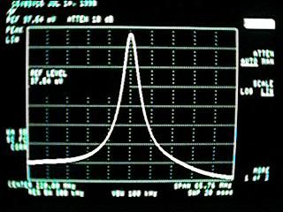
The spectrum analyser picture above is taken using the cavity as a band-pass filter (diode removed). The slope varies quite a bit so recovered speech is loudest and the highest quality if the cavity is only slightly off-tuned. I just threw this cavity together to show you the pictures, but I think you get the idea. With a little more care, symetry and attention to detail then the slope will become more linear. One "interesting" (ie. useless) effect is that if you receive an FM signal with a 1KHz tone and the cavity is tuned 'dead center' then the recovered modulation becomes 2KHz but at a lower AF signal level. This effect can be used to tune the cavity to precisely (for example) 145.7375 MHz so that you can receive 145.750 (and 145.725 MHz) with the best possible sensitivity and quality.
This project may also be used as a TX/RX filter by using 2 identical input/ output loops, but you will need to experiment with the loop size. The analyser picture also shows the insertion loss to be about 5dB but with a little care and internal silver-plating you should be able to reduce losses still further. Do NOT forget to wait until your wife, (or mother) is out when you build this project, or you could end up in the same divorce court as other radio amateurs who have built this project.
Dont forget to visit my messageboard if you have any questions about this or any other project. I always look forward to receiving feedback, positive or negative. You do not have to register to post messages.
Very best regards from Harry Lythall
SM0VPO (QRA = JO89WO), Märsta, Sweden.
EA/SM0VPO (QRA = IM86BS), Nerja, Spain.