
For me this is a very interesting project. It was created November 2019 when I was on one of my monthly jaunts to Spain and had no workshop facilities whatsoever. Not a sausage!! On this occasion I had no rig with me, so EA/SM0VPO was totally inactive, but my mind was still active.
I have for a long time been experimenting with a retro-style oscilloscope (using a CRT, 1200-Volts, big sparks, valve heaters, etc), but I found loads of small "niggley" things that I don't like. Everything feels like a compromise. Here is the circuit diagram of the original:
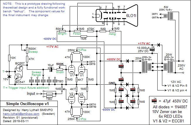
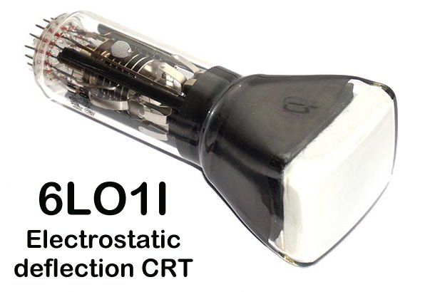
Theoscilloscope CRT is a nice little Russian 6OL1I. Here is the CRT datasheet. As you can see, the deflection requires about 90 Volts for every cm, so the 5cm tube needs about 450 Volts (+225 V and -225 V push-pull on opposite deflection plates). That is why I chose to use ECC81 triodes.
The original timebase generator used the BC547 and BC547 in a classical relaxation oscillator. The problem was that it was not so linear. I tried using 35 V DC, but the curve was still visible. I even tried using a buffer transistors and "bootstrapping", which made it quite a bit more linear. But with low values of timer capacitance the oscillator stops. The sawtooth waveform for the horisontal sweep can be generated using a couple of triodes. Great!! I tried several published designs, but none of them were suitably linear enough for me. In addition, trigger functions were really crude: ok for audio, but rubbish for modulation.
The sweep linearity and trigger I believe to be the most important part of anyoscilloscope, without which you can never get a stable trace and do meaningful measurements. That is why I am turning to a bit of digital electronics. So for my sweep generator I eventually want:
Ok, I will not promise all of that in one go, I am not a politician. I have done loads of experiments with sawtooth waveform generators, many using old valve (tube) designs. These tend to have several flaws, such as:
After a while I realised that, while my basicoscilloscope is working, it is crude and it needs some re-thinking. This project is the starter project for that re-work. As far as I am concerned, my 1200-Volt power supply is perfect for my needs, and the ECC81 tubes are good high-voltage drivers for the CRT deflection plates. So the first stage is to work on the sweep generator. I shall keep thermionic valves, but add transistors, CMOS integrated circuits, and possibly even a small PIC micro-processor, if the need arises.
Today I shall begin with only the BASIC sawtooth CMOS waveform generator, with access to key points of the circuit using a plug-in interface/connector card for experimenting. The basic sawtooth generator frequency will be variable by a potentiometer, and switched capacitors to select the ranges. I want the potentiometer to have a 10:1 frequency range. I also want to have very low sweep times (1 second) and up to 100KHz so I can view up to 1MHz. The next interface card will also have pads for the addition of resistors or diodes.
The sweep / timebase generator is based on a previously proven design for an EPROM signal generator. Binary waveform values were burned into an EPROM so that selecting different pages of memory gave different waveforms, or even sound recordings. To generate a sawtooth waveform I do not need an EPROM, just a binary count. The circuit line-up is like this:
One point worth mentioning is that to get 8-bit resolution, the divider must divide by 256. To get a 100kHz sawtooth waveform then the VCO will have to run at 0.1MHz x 256 = 25.6MHz. Now this is somewhat pushing the standard CMOS chips a bit, and not even the British Prime Minister could make that promise. But HEF4046, 74HCT4046 and 74HCT9046A should all go that high with a 12 Volt supply voltage. The CD4046BE has an upper limit of about 1MHz at 5 Volts, but at 12 Volts it will go a lot higher, certainly well over 12MHz. When I was playing about with EPROMS I had one up to over 15MHz. Use the faster variants of the 4046 for the best chance of success.
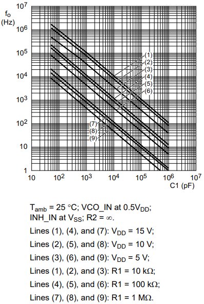
R1 (10K) and the capacitor Ct determine the operating frequency. The recommended minimum value is about 40pf but you can get the VCO to run with almost zero pf here, just the residual capacitance on the earlier board I tried. R2 (300K) is an offset that increases the VCO frequency and limits the VCO tuning range. Here is an extract from the HEF4046 application data:
If you use a cheap CD4046BE and cannot get it up to 25MHz, then you can use the interface board and build a 7-bit D-A R2R ladder only for the maximum scope range, so you only need 12.8MHz. Then use an 8-bit, or 9-bit D-A for the slower ranges. With the interface board you can have two D-A converters, one for 7-bit and one for 8-bit (or 9-bits?). If you do use a 7-bit D-A then you may need a small capacitor of typically 10pf across the output to sort of smooth off the sawtooth ramp a little, if it is visible. Since the counter is a "ripple counter", a change will be rippled down the counter chain, which can give rise to small glitches as the counters catch-up. The 10pf will also smooth these out. This is not a problem at slower counting speeds.
Otherwise, the basic unit could not be more simple. The external interface or connector card can be plugged in, giving access to the counter Q1 to Q9, the reset pin, and power. The basic card counts 0-255 and so the analogue output has only 256 steps. This will be quite adequate for a small 6cm tube.
The interface card also has access to the counter Q9 output, so it is possible to increase the steps from 256 to 512. Q9 can also be used in a trigger circuit to stop the VCO until a trigger is detected, but that will come later on in the project. For the moment, the "Rs" port must be grounded for the counter to work. This part of the project is wide frequency and linear sweep.
The unit is powered from 12-Volts DC so that the analogue output is more than sufficient to drive an ECC81 valve grid. The ECC81 grid impedance is so high that we can forget about the valve loading the R2R network.
That's it. It couldn't get any more simple. I will now give you the PCB and layout files.
Here is the complete circuit diagram of the basic sawtooth sweep generator. I have shown every PCB wire-link (W) in the drawing, as well as the interface connector points. I have not numbered the interface connectors, but this should be failrly obvious.
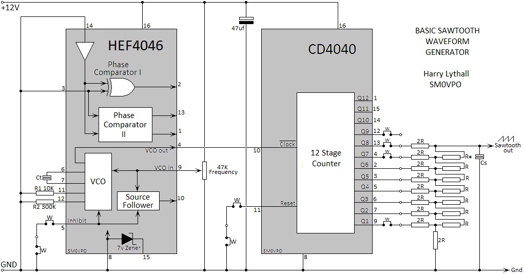
As you can see, I have deviated from my usual circuit blocks and shown a lot more detail, especially as to what is inside the two ICs. Since this is an experimental project, it may help you if you intend to build the untested prototype. I am failrly certain that it works as this is almost a duplicate of my EPROM AF signal generator. The only thing that has changed is that the EPROM is no-longer required.
In the event that the chips are NOT suitable for VCO=25MHz, then the 10K resistor R* can be removed, and a the sawtooth waveform taken from the PCB port formerly used by R*. This will convert the generator to only 7-bits for the upper sweep, and Cs added (10pf?) to smooth the waveform. The interface connector can then be used to add a 9-bit D-A converter for all other ranges. This is one of the things I have yet to confirm.
The capacitor Ct will be connected by means of a couple of terminal posts, and the capacitors soldered directly on the range switch on the instrument front panel. A little tip, if you want 1mm connector strips and flat-cable with 1mm plugs fitted, then you to your Arduino shop. The 1mm plugs also fit well on valves, if you don't have the correct valve base. They only need a gentle first-push.
Otherwise everything else is ridiculously simple: oscillator -> counter -> D-A.
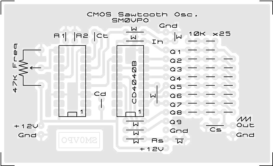
The main PCB is 48mm x 78mm. The interface/connector PCB is 38mm x 19mm. These drawings are unusual in that this is the first PCB that I have published where I have not drawn with a pen on a drawingboard & scanned, or drawn in a picture drawing program, such as MS-PAINT.EXE. This was laid out using Proteus 7.7 Professional. I am still learning the program, so I have maybe done a few things the long-winded way. But here is a view of the PCB and the component layout:
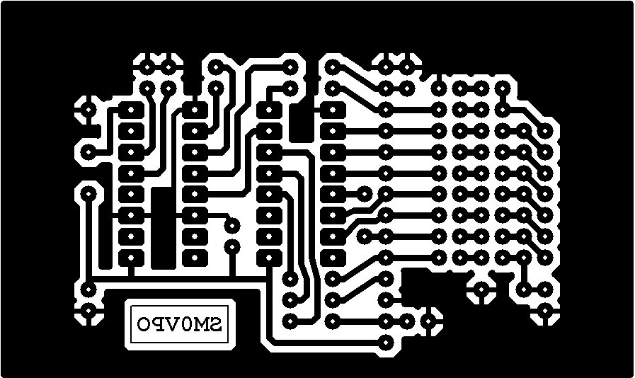
All holes are 1mm Dia. As you can see, all ground (Gnd) connections have a thermal-break to improve soldered joints, and stop solder spreading over the ground copper like "cat-pee on a keyboard".
There are a few items that should be clarified. There is an optional 14-pin connector so that all connections to and from the board are available at the connector, with the exception of the frequency potentiometer (linear 47K) and the sawtooth waveform out. The 14-pin connector strip has Gnd at the top, +12V at the bottom, and Q1-Q9 somewhere in the middle. If this connector strip is NOT used then the two wire-links marked "W", beside the Rs and Ih pins, and the two "w" links beside CD4040 pin-8 should be fitted (the three "W" links beside CD4040 pin-1 not needed). Other notes are:
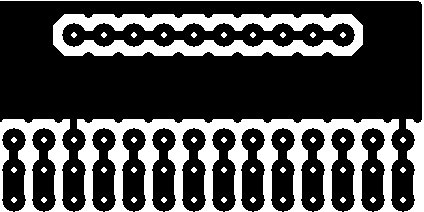
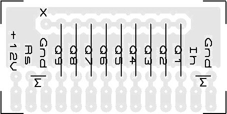
Here is the proposed connector/interface board, but this is only a starting point. This particular board is designed to take diodes to decode the counter.
An interesting point here is that a nice little resistive D-A can be built using fewer components, by summing together all the digital ports using a single resistor for eack port: Q8=5K, Q7=10K, Q6=20K, Q5=40K, Q4=80K, Q3=160K, Q2=320K and Q1=640K. Ok, they are not common values, but you can make up a really nifty, low-component count D-A using these values. Just a bit of extra info :-)
The Interface/Connector board will be further devloped, depending on how the basic generator board performs. The idea behind the interface PCB is that it can be plugged into the 14-pin header on the main board, and act as a plug to allow connections to a second board. The second board will be used for trigger and such. It can also be used for a 9-bit D-A converter, instead of the 8-bit D-A on the main board. Note that the Rs and Ih links should be removed from the main board and used on the interface board if needed. You may need these pins for other functions, for example, to stop the VCO while waiting for a trigger pulse to arrive.
The Q1-Q9 pins can also be used to form AND or OR gates using diode logic. This can be used for the trigger circuit to detect the end of the sweep, either in 8-bit (Q9 only) or in 9-bit (Q1 to Q9). The Rs input can be used to clamp the binary to "00h" while waiting for a trigger, or to clamp the sawtooth output waveform to 0V if there is any flyback visible on the screen.
This is not the end of this project; this is just the beginning. If you have any good ideas or suggestions then do not hesitate to contact me.
I hope that this project has given you some "food for thought". You can always e-mail me at harry.lythall@[my domain].com. You can even use oeieio@hotmail.com or hotmail@sm0vpo.com as they are both valid e-mail accounts for me ;-) although I would prefer that you visit my messageboard if you have any questions about this or any other project. I always look forward to receiving feedback, positive or negative ☺
Very best regards from Harry Lythall
SM0VPO (QRA = JO89WO), Märsta, Sweden.
EA/SM0VPO (QRA = IM86BS), Nerja, Spain.