
There was a bit of activity for my DC-DC voltage converters around the turn of 2001/2002. Several people built them and had problems. The basic problem with the DC-coupled arrangement I chose was that it is efficient, but if there is a single wiring error, then transistors burn and usually with a nice pyrotechnic display. Here is a simpler version that is much more forgiving and can be built in stages. I was prompted to build this circuit to power a DF96 valve (tube) radio from a 12v supply, so four PCBs have been drawn, each able to provide the following voltages.
| VOLTAGES POSSIBLE WITH THE PCBS GIVEN | |||
|---|---|---|---|
| PCB filename | Links LK2 to LK4 are all RED | ||
| LK1=RED | LK1=RED | LK1=BLUE | |
| vconv_24_pcb.gif | +12 volts | +24 volts | -12 volts |
| vconv_36_pcb.gif | +24 volts | +36 volts | -24 volts |
| vconv_48_pcb.gif | +36 volts | +48 volts | -36 volts |
| vconv_60_pcb.gif | +48 volts | +60 volts | -48 volts |
| Don't worry about all the link combinations, I will give you these later. | |||
The basic circuit consists of a 50KHz square-wave oscillator that is free-running and does NOT rely on any form of return path via other external components. This reduces efficiency slightly, but makes the circuit much more stable for constructors. The collector of one of the oscillator transistors drives a PNP/NPN complementary output pair, but no provision has been made to reduce crossover distortion. No-one is going to listen to it.

Remember that this circuit has no current-limiting facilities. If you place a short-circuit on any output then expect something to get hot - it will! I have overloaded it a few times, generated the odd burnt finger. Switch off the power, wait a minute and it works again when you put the power back on. I love the BC547/557 for this reason, if not for the fact that they are cheap!
The multiplier circuit shown (to the right) is repeated as many times as needed. It uses just two diodes and two electrolytic capacitors to make a copy of the input voltage and add it to the original voltage. In this way it will add 12v to give 24v. Build two multiplier stages and the voltage will rise to 36v. The PCBs in the ZIP file go all the way up to +60v. Since the output current capability reduces as the voltage rises, so too does the need for the 10uf capacitors. With 60v, only 2.2uf at 64v working is necessary. This will still fit on the PCB if you get the right component. An alternative method is to use only ONE multiplier board as shown and then the remaining multipliers are modified, still using low voltage (16v) 10uf reservoir capacitors. The coupling capacitors, however, still need to be of a suitable voltage rating. This modified multiplier is NOT supported on my PCB.
The links LK(x) refer to the links on the PCB component overlay. If the LK1 RED wire is removed and the BLUE wire is fitted, then the circuit will provide +12v, +24v, +36v and +48v. The first option (+12v) may not seem very usefull since this is the same as the input voltage, but if all electrolytic caps and diodes are reversed, then the board will provide -12v, -24v, -36v and -48v.
The board can also give a wide combination of voltages out. Consider this component overlay drawing for the "VCONV_60_PCB.GIF" printed circuit board.
If LK1, LK3 and LK4 remain in the RED position, but LK2 is set BLUE, then the outputs from the board will become (+12v from the input) +24v, -12v, -24v and -36v. I can show you this much better in a table (if I can still remember the HTML!):
| LK=RED | LK=BLUE | Outputs from the board (left to right) | Reversed* |
|---|---|---|---|
| LK1 LK2 LK3 LK4 | None | +24 volts, +36 volts, +48 volts & +60 volts | None |
| LK1 LK2 LK3 | LK4 | +24 volts, +36 volts, +48 volts & -12 volts | Mult4 |
| LK1 LK2 LK4 | LK3 | +24 volts, +36 volts, -12 volts & -24 volts | Mult3 + 4 |
| LK1 LK3 LK4 | LK2 | +24 volts, -12 volts, -24 volts & -36 volts | Mult2 + 3 + 4 |
| LK2 LK3 LK4 | LK1 | -12 volts, -24 volts, -36 volts & -48 volts | Mult1 + 2 + 3 + 4 |
| * = Electrolytic capacitors and diodes in the indicated multipliers are reversed. | |||
Rather versatile! Is that neat? or is that neat?
Why is the board picure backwards Harry? Easy! When using Photo-Etch techniques to make PCB's, the ink will be on the top of the film. Lay the drawing on the sensitised copper-clad board so the writing is correct when viewed and the ink is in direct contact with the board. If it were otherwise then there would be a gap between the ink and the board (the film thickness) where light could creep under, resulting in a poor quality PCB.
When printing the artwork for photo-etch, DO NOT SCALE THE PICTURE FILE but select the printing scale from your graphics printing program. If you reduce the picture file then you will loose detail. If you are using PSP (PaintShop Professional) then from the FILE pull-down menu, select the PAGE SETUP. Then select the scale factor of 38%. Do not check the FIT TO PAGE checkbox or you cannot set 38%.
Now print the page as normal. If you have a laser printer then just pop some OHP film in the hopper. If you still only have a dot matrix printer then you you have my deepest sympathies!
The unit will deliver about 1 to 2 watts TOTAL output. This is because the transistors can deliver a current without a significant voltage drop since they are either switched ON, or OFF: there is no situation where they have both voltage AND current exposure. The oscillator draws about 15mA at 13.8v and this drives the PNP/NPN output transistors sufficiently hard to give around 100mA from the unit at +24v (or -12v). You could use heavier transistors here to more current, but I decided to stick to the BC547/557. At +36v (-24v) you can only expect 50mA. At +60v (-48v) this will fall to just a little under 30mA. It may not be much, but it is enough to charge NiCad and NiMH batteries and more than enough to power a vintage battery radio, such as my Vidor 381, which draws only 7.6mA at 90 volts. The converter is even enough for continuous trickle-charging of a car battery from another car battery.
I used to have an old Austin Morris 1100 that had a +VE Earth system. I used this circuit (a PNP version) to constantly trickle-charge another battery for my hamradio set. If you are using the device as a charger, then use a torch bulb as a limiter resistor to restrict the current.
Yes, there were several built. One version used two sets of NPN/PNP complementary transistors, each working from opposite sides of the oscillator. By using parallel multipliers it formed a sort of "full-wave" which more than doubled the output current capability. But, let us come back to that which still survives today.
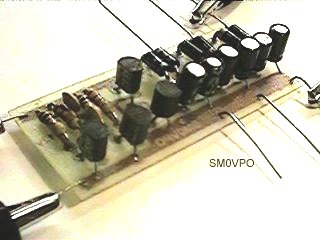
The prototype PCB versions described above have been built in many forms, but the latest one I built used three multipliers to give me my original +13.8v, then generate +24v, -12v and -24v. The photographs below show this version completed, and driving a 28v 60mA tungsten-fillament lamp.
I also mentioned that I used this to power a 90v battery valve (tube) radio. I built the unit into a cardboard battery box and used an add-on multiplier board (a sawn-off prototype failure) to get the 90 volts needed. This was stuffed into the box with 14.8v NiCad batteries. There are four wires from the box, +90, Ground, +14.4v and the positive input from the converter PCB. The last two are for the switch and also enable me to charge the battery via the Ground and +14.8v terminals.
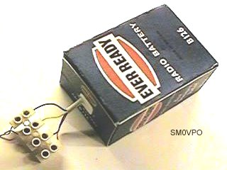
Incidentally, if you are interested in vintage radio then the battery "skins" have been scanned. All you need to do is to print them to a colour laser printer, glue the printout to a sheet of card, cut it out and glue it together. I will not post the skins since they are not my own work and I cannot remember from where I downloaded them. I shall look into that and update this page if I have any new information.
As you will appreciate, it can cost a lot of money with high-voltage electrolytic capacitors, but there is a way to reduce costs by using all low-voltage capacitors in the classic "cockroft ladder".
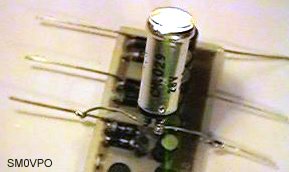
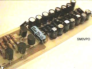
Here the lower hosizontal row of capacitors are each charged with about 12vDC, but the upper hosizontal row of capacitors also contains an AC component. In this way it is like an elevator lifting a few volts up just one floor at a time. All the DC voltage components are added, but each capacitor has only 12vDC across it. In this way you can generate several 100's of volts using a bag of low-cost and low-voltage electrolytic capacitors. With a 13.8v supply, the 22uf must be rated at 25vDC, all other capacitors only need to be rated at 16v. A PCB has already been designed for this particular circuit and it too can be found on the Download section of my homepages. The prototype looked like this. The left photo is the completed project showing the oscillator at the left of the picture, and the multiplier to the right. The right-hand picture is a close-up of the multiplier chain. It is a bit cramped, so every few diodes I had to leave one a little higher than the others.

The disadvantage of this particular circuit is that eight-multipliers are needed to get 95 volts with a 12.5v supply due to the accumulated voltage drops of all the diodes that are effectively in series. Efficiency allso falls off a lot since the AC leg conducts the AC component through a series of capacitors, each with it's own additional loss. The circuit shown will provide about 3mA at 90 volts, which is just about enough to power a 100mW battery-valve transmitter using a single valve. To improve the efficiency you would have to use capacitors with a much larger value, say, 1000uf, but then for the additional cost you would be better off using the multiplier in the previous section where one AC coupling capacitor is used for each stage. I have included this circuits since you may often need a fair few volts with no current behind it. This circuit is both simple, cheap and will privide 3mA at 90 volts for under 50mA of 12v battery current.