
WARNING - This project generates lethal voltages and can develop a fire hazzard in the event of a fault. If you are not capable of handling these voltages then do NOT attempt to build this project, without supervision from someone who is qualified. This project is NOT suitable for children or beginners.
This project is a development of my "alternative power" project, given on the web at psu_inverter_01.htm. In the power project I showed you how I generated 50/60Hz (ish) at 50 Watts, sufficient to drive at least four of those 11W economy lamps, and to build the circuit in 15 minutes, without soldering. I also showed you how I built larger inverters, using bipolar transistors.
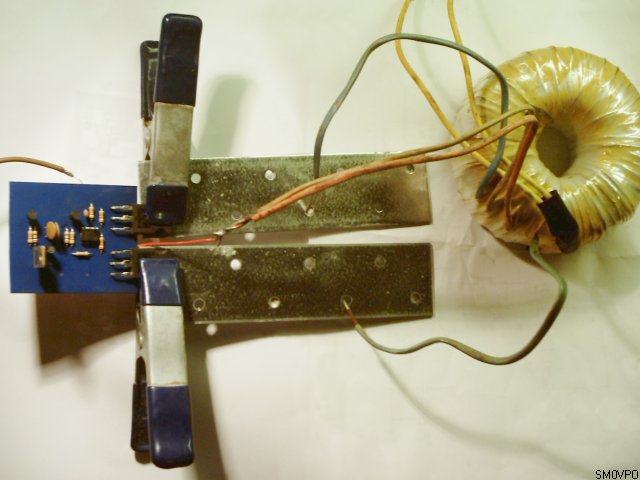
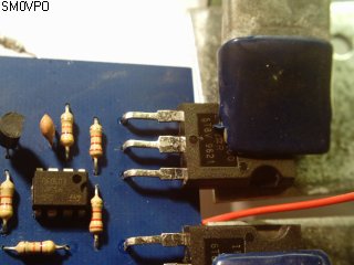
This new project is an extension of that project, but this one does indeed need some soldering expertise. It can easily generate typically 500 Watts, continuously. As a kit I will supply the transistors and transformer to generate around 40 Watts. Here is the circuit "lashed together" and generating about 400 Watts. The board is 2.1" by 2.4" so it gives you a good idea as to the scale of the picture.
This DC-AC inverter is a lot more frequency-stable than the 15-minute DC-AC converter and it can be built to operate with battery voltages from 12 Volts to 48 Volts. The basic advantages of this unit are:
Yes! the same board will work with a small 10 Watt transformer, but also with a 1000 Watt transformer. If you find a source of these transformers at a "reasonable price" then please drop me a line.
The heart of the circuit is a simple multi-vibrator oscillator, TR1 and TR2. I have chosen BC547 because I have a lot of them, but BC108, 2N2222, or just about any silicon NPN transistor will work here. The frequency is determined by the 0.1uF and 120k (100K) resistors, R1 and R2. Use 100K if you want a 60Hz (ish) operating frequency. If you use the unit indoors in a temperature-controlled environment then simple and cheap ceramic capacitors are adequate. Otherwise you should use "Polystyrene Film" (polyester or polypropylene dielectric), which have excellent temperature stability properties.
The multi-vibrator output, in principle, could be fed directly to the gates of power field-effect transistors, but for best efficiency we want them to be turned 100% ON, or 100% OFF (notice how I avoided the use of the term "hard on" :-). If you analyse the collectors of TR1 and TR2 you will find that they do NOT generate a nice square-wave. They look like this:
That positive slope is a problem. If the power transistors are only 1/2 ON, then they will dissipate (waste) power. The time interval between OFF and ON may be small, but it is enough to cause the output transistor to dissipate power. If it dissipates just 2% then at 500 Watts my modest heatsink will cook. I want to have a nice, clean square-wave. But I can also use this slope to cause a delay, so there is a moment of pause between the two power transistors ON time. This will avoid any overlap.
This is done by the operation amplifier, IC1, which switches ON and OFF cleanly and also functions as a level detector. When the collectors of TR1 and TR2 have reached about 11 Volts (in the centre of the circle on the scope picture), then IC1 will change state. With this clean 0 - 12 Volt square waves to TR3 and TR4, they are hard-off, or hard-on (sorry!!). So let us look at the modified circuit:
Notice the 1uf non-electrolytic 400vDC working capacitor clanked across the transformer 230v AC winding. This capacitor takes away the spikes that could possibly damage sensitive equipment. If you want to be really nice, then a choke-input PI-filter, comprising 10mH chokes and 10uF non-electrolytic caps, would make the output sort of resemble a sinewave. This would make the unit suitable for other more sensitive equipment, listed further down this article (under do NOT connect).
The transformer is any AC mains to low-voltage transformer with a split secondary. I use it backwards. A 12v-0-12v to 230v (115v) that will handle the current is perfect for 12 Volt, 250 Watt operation. A 24v-0-24v to 230v (115v) is about the best compromise for up to 500 Watts. You need 48v-0-48v to 230v (115v) if you want to go up to 1000 Watts. You can parallel transformers, as long as they are identical. A 0-24v + 0-24v to 230v can have the two secondaries wired in series to form a 24v-0-24v to 230v transformer.
A suitable source of low power transformers is scrap HiFi amplifiers. They often have a 30v-0-30v that will deliver mains voltages from 36v DC. They are usually good for over 100 Watts. Battery chargers are also a suitable source, but you can rewind a 500 Watts mains isolation, or 115/230v converter transformer.
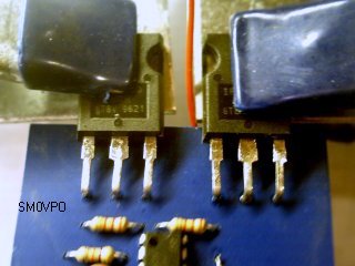
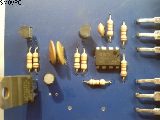
All the components, except for the transformer, are mounted on a single-sided printed circuit board. The field-effect power transistors are also fitted to the board, but they are mounted on a heat-sink and provide the support for the board. The board is not to be bolted down to anything.
Pay particular attention to the components, especially the orientation of the transistors and the 10uf electrolytic capacitor. I hate to admit it, but I got a bit of a shock with the first prototype of this board. I made the basic mistake of fitting the electrolytic capacitor the wrong way round. These "little-buggers" DO make a loud noise!
The power transistors are to be mounted on two separate, insulated heat sinks. These are also the connections to the transistors, so they must NOT come into contact with each-other, or the unit chassis. You only need approximately 20 square-centimetres of area, but even that is much more than is really needed. The heat sink is more fore safety than necessity as the prototype will deliver 250 Watts continuous without any heatsinking at all :-). I used these ready-made brackets as heatsinks, bought from my local builders, and held them in place with groundsheet clamps.
In operation you need to have a fuse in the battery lead. If you intend to load the inverter to 500 Watts, then you will have a current of 45 Amperes at 12 Volts, or only 22 Amperes at 24 Volts. At 48 Volts battery voltage, the current will halve yet again to 10 Amperes.
TR3 and TR4 can be selected for the purpose. I have used IRFP260 HEXFETs, which are excellent animals. If you apply 10 volts to the gate then they have an ON resistance of typically 0.055 Ohms. They will handle over 45 Amperes, with the odd spike of over 150 Amperes. They will also tolerate up to 200 Volts. The problem is that they cost money. Lots of it! For modest 24 Volt to 115/230 Volt "caravan power" unit, then the IRF540 would be a good compromise between money and power. You should be able to pull 200 Watts from a pair of those. Here is a quick comparison chart between some devices.
| Device | Power (max) | Vds (max) | Id (max) | ELFA price |
|---|---|---|---|---|
| IRF710 | 36 Watts | 400 Volts | 2 Amperes | US$ 1.00 |
| IRF510 | 40 Watts | 100 Volts | 5 Amperes | US$ 1.50 |
| BUZ80A | 75 Watts | 800 Volts | 3 Amperes | US$ 14.00 |
| IRF540 | 150 Watts | 100 Volts | 30 Amperes | US$ 4.00 |
| IRFP260N | 300 Watts | 200 Volts | 50 Amperes | US$ 11.00 |
| STE180NE10 | 360 Watts | 100 Volts | 180 Amperes | US$151.00 |
I have used www.elfa.se for some transformers. The device you select must be rated at least 4x the battery voltage you are using. One thing to remember when playing with power is that when things go wrong there is usually a violent pyrotechnic display, so select devices with a good margin.
In case you did not know, power transistors contain a little silicon and a lot of smoke. The smoke is hevily pressurised, which is why these devices are so expensive. If you let out the smoke then they will stop working.
All the components fit on the PCB, and the power transistors are used to support the board. I have not used the current restrictor lamp for the prototype, mainly because I am too damn lazy. I also feel that I will not make another mistake and blow any more components sky-high. But I will fit the lamp before I put the board into full-time service. Here is the completed PCB:
When testing, do NOT be tempted to use aligator-aligator leads for battery connections, or you could suffer burns to your hand in the event of a wiring fault. Lead-acid batteries can deliver a dangerously high current.
If you have an oscilloscope handy, then apply power to the board, before the transformer is connected. Look at the gate terminal of each power transistor. There should be a nice clean 0 - 12 Volt square-wave. If you have an analogue Multimeter, then check that there is about 6 Volts DC present at the same terminals, with respect to the battery negative terminal. If you measure the AC voltage between the TR3 and TR4 gate terminals you should see 12 Volts.
Bolt the transformer wires to the heat sinks and connect the battery positive to the transformer. The battery wires must be rated at least 5 Amperes, minimum. This means at least 1.5mm Diameter conductor (1.8mm cross-sectional-area) (14-AWG, 16-SWG). You can now load the inverter to 100 Watts at 24 Volts (50 Watts at 12 Volts). Here is a simple table to give you an idea as to the minimum wire sizes needed:
| 12 Volt Power | 24 Volt Power | 48 Volt Power | ||||||||||
|---|---|---|---|---|---|---|---|---|---|---|---|---|
| Power | Amps | Dia. | AWG | SWG | Amps | Dia. | AWG | SWG | Amps | Dia. | AWG | SWG |
| 50 Watt | 5 A | 1.6 | 14 | 16 | 2.5 A | 1.1 | 18 | 18 | 1.3 A | 0.8 | 21 | 21 |
| 100 Watt | 10 A | 2.1 | 12 | 14 | 5 A | 1.6 | 14 | 16 | 2.5 A | 1.1 | 17 | 18 |
| 150 Watt | 15 A | 2.5 | 10 | 13 | 7.5 A | 1.8 | 13 | 15 | 4 A | 1.3 | 16 | 17 |
| 250 Watt | 25 A | 3.3 | 8 | 10 | 12.5 A | 2.4 | 11 | 13 | 6 A | 1.7 | 14 | 16 |
| 350 Watt | 35 A | 4.1 | 6 | 9 | 18 A | 2.9 | 9 | 11 | 9 A | 2.0 | 12 | 14 |
| 500 Watt | 50 A | 4.7 | 5 | 8 | 25 A | 3.3 | 8 | 10 | 12 A | 2.4 | 11 | 13 |
| 750 Watt | - | - | - | - | 40 A | 4.3 | 6 | 9 | 20 A | 3.0 | 9 | 11 |
| 1000 Watt | - | - | - | - | - | - | - | - | 25 A | 3.3 | 8 | 10 |
NOTES:
The unit described here will provide a reliable AC power source. Bear in mind that this unit does NOT deliver a sinusoidal (sine) waveform, which means that power controllers using "phase angle" control, such as drill-speed regulators, dimmers, and heating element controllers, will not function. The unit will remain 100% ON or OFF.
Many "synchronous" motors require a clean sine wave if they are to operate without burning out. The old "squirrel-cage" motor may overheat. This includes desk and ceiling fans, and those old-fashioned record-players and reel-to-reel tape recorders. Most central heating pumps also need a clean sine wave.
This DC-AC unit is also based upon a free-running oscillator. This means that the frequency is close, but not accurate, which is the price you pay for a simple unit. Your digital bedside clock may gain or loose a couple of hours a day, but the radio will work. You can forget about your video tape recorder timer, but you can use the VCR for normal recording and playback.
You can, however, use most items domestic items, such as your cell phone charger, computer, modem, lamps, TV, in fact 90% of your electrical apparatus will work. In general, if the unit has a transformer input, or one of those external little units you plug into the wall to get 12 Volts, then it should work fine. But here is a short list of some items that will and will not work:
| Ok to use | Do NOT use |
|---|---|
| Cellular telephone charger Electronic test equipment Computer, Printer, Modem Computer monitors Tungsten lamps Fluorescent lamps "Economy" lamps Radio, TV, VCR Satellite/Terestrial receiver Locks, security, CCTV AC/DC motors, drills, saws Chargers, starters, heaters Transformer input equipment Oil-fired boilers/heaters Fire/intruder alarm "Battery Eliminator" units Toys, Train-sets, etc All valve (tube) equipment. |
Ceiling fans (brushless) Phase/synchronous motors Phase-angle control units Clocks, 50/60Hz dependant units Lamp dimmers Drill speed controllers Synchronous central-heating pumps Older record turntables |
If you are unsure, then do not risk using it. If you do want to "give it a go", then observe it when you try it. If it fails to operate then unplug immediately. If it does work, then keep an eye on it for a while, making sure there is no overheating. Most transformer-input equipment will usually run more efficient with a square-wave.
The above text will give you a good idea as to how to build this project, and to modify it for other power levels. The result is a DC-AC power supply unit that will deliver power continuously in the event of a power failure. In principle there is no maximum limit to the power you can get out of it. The power field-effect transistors draw no gate current, which means that you can build the unit for 500 Watts, then add another TR3/TR4 pair and a transformer to get 2x 500 Watts. Feed the new pair from IC1 via another two 2K2 resistors. IC1 will deliver enough to feed eight or more sets of power transistors, which means that a 4000 Watt (8x 500W), 6000 Watt, or even an 8000 Watt (8x 1000W) inverter, is quite practical.
A nice little trick for low power levels is to run equipment from this DC-AC unit continuously, but "float-charge" the batteries with conventional battery charger. The charger must be capable of delivering twice the current drawn by the DC-AC power unit. This will in effect give you an un-interrupted power supply. If the main supply fails then you may never even know it has failed.
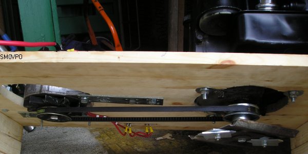
If you can afford to buy a solar-panel, or have a wind-mill that can supply enough current, then you can also save money by charging the battery at the same time as you use it. You will probably never be able to become independent of the main power utility company, but you will be able to reduce the money you pay them. A couple of car generators on a board can be powered from a simple lawn-mower engine, and this is the solution Magnus, my step-son, has used on his girlfriend's island. Magnus is using a 12v system so he used just one generator:
If you are uncertain as to whether a piece of equipment will work, then do not try it. I will not accept any liability for any damage, how-so-ever caused by the use of this project. It is your responsibility when you plug the equipment in.
Very best regards from Harry Lythall