
2021 has been an eventful year for me, mainly at work. I have done a lot of HF operating /Portable around 7MHz, 14MHz and 18MHz in my lunch breaks. From the end of September I experimented with a 1.3m long telescopic whip and a loading coil on a home made mag-mount, but then the cold weather and Christmas put a stop to my lunch-time HF activities. I will save that for another article as soon as I can test the new prototype on the air.
So with temperatures of -19°C, and unable to operate short wave from home during daytime, this made me turn to VHF and UHF. I do not really think about VHF for serious distance because I have limited antenna space, and I have already taken liberties with my HF antennas and the local council. For me the VHF bands were to be background noise, monitoring the local repeater when I am in the workshop doing other things. Occasionally I would have chat if there was something interesting. I pulled out my trusty FT-290R that has been laying in storage after we sold the house in Lunda, eight years ago. I charged the 12V VRLA battery and tried to access "the usual" local repeaters.
Nada!!
Where have all the repeaters gone over the past 8 years? Something has happened! While I was in Spain the rest of the world has continued to revolve without me and there have been developments.
I left my FT-290R scanning for a couple of days and sure enough I heard CW identification transmissions. So there is still some life on VHF. I googled for "repeater access" and it seems that many of them have gone digital; the 1750Hz tone-burst is almost a thing of the past, and in the UK it is illegal. There are also other modes with "colour codes" ... And what all is this "Brandmeister network"? Thankfully I was able to find a few repeaters with analogue access. For that I need to equip my old FT-290R with "Tone-Lock", "CTCSS", or a "sub-audio tone" (a beloved child has many names). That function was not built into my radio back in the 1980s, probably before many radio hams were even born. There is no way I am paying money so I can just have comforting background noises and the occasional chat, so I have to build something myself.
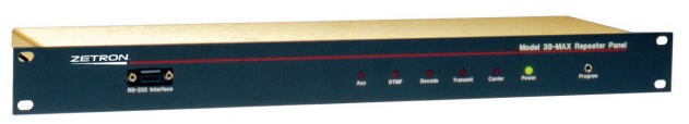
In the 70s and 80s I worked on "Community Repeaters" professionally where several competing companies could share a single repeater and still have private conversations within their own fleet of mobiles. If one mobile user, for example a taxi, were to transmit, then a sub-audio tone on the transmitter opened the repeater, identified the user, and the repeater transmitted the same tone code to the same fleet of mobiles. This tone code locked-out all the other companies that were sharing the repeater, inhibited their transmitters, and closed the receiver squelch - channel busy. I installed a few of the Zetron CTCSS control panels on hiltop repeater sites, and installed CTCSS modules in 100's of mobiles.
For amateur VHF and UHF amateur repeaters this is not the case, we do not want to lock-out anyone. One only needs to include a continuous tone during transmission to enable a repeater. All users have the same tone, but different repeaters have different tones. Receiver CTCSS squelch could be used to listen to one specific repeater, if you had several repeaters on the same frequency and providing the repeaters also transmit the same tone. I don't have this problem in Märsta. I am just grateful that they did not use Selcall or anythingelse exotic.
The only thing I feel saddened about is that it appears you may scan and find a repeater, but the only way you can find the frequency of the CTCSS access tone is to either surf the web and look up the repeater from the CW ident, or try all 50 combinations to find one that works. Neither of these options is really practical if you are travelling. Perhaps I am missing something obvious?
The easiest way to transmit a tone is to inject it into the microphone inside the microphone case, but there is a size limit. There could also be a restriction with this solution, depending on the transciever. Many of the better quality transcievers have an audio filter that restricts the transmitted audio bandwidth from typically 300Hz to 3400Hz. Others may simply have a 3400Hz low-pass filter. If your radio has a lower frequency limit, then you will have to inject the tone after the audio processor. It is just a question of looking at the circuit description in the manufacturers manual.
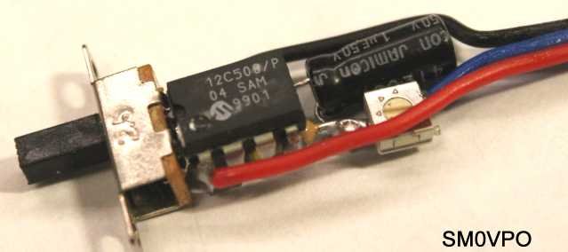
So how many different tones do I need? After doing a bit of research I found that in my situation, all I need is a choice of two tones: 77Hz and 123Hz. Problem solved. My CTCSS tone generator has two channels, and it is only about 28mm x 13mm x 6mm. It would have been half the size if I had used a miniature electrolytic or ceramic capacitor in the filter. The audio level was ok for 77.0Hz but for 250Hz it would be a good idea to change the 1μf for a 100nf to get a higher audio level. It all depends on the microphone sensitivity. "Rats nest" construction allows you to form the shape of it, but a PCB would have made it somewhat larger. Mine will even fit inside the recessed plastic P.T.T. button in my microphone! I will not butcher my "original" radio microphone, so I may use the 3D printer to make a new microphone button that will accept a small PIC processor.
I programmed a little PIC12F509 (and PIC12C508) 8-pin DIL baseline microprocessor to generate one of two tones. The circuit is really simple: +4.7V DC to the chip and a dropper resistor to feed the microphone from the TTL output of the chip. Split the resistor using a pot and another resistor, add a capacitor and you have a simple Low-Pass filter. Stuffing a square-waveform into a microphone is not a particularly good idea.
The software is really simple, it is an endless loop that toggles an output port after a preset delay. That delay has 50% of the period time of the wanted frequency. Before the delay is called, the GP3 input port (pin 4) is tested to check which tone is wanted. The main routine calls one of the two time delay routines. The tone frequency selection must be checked with every iteration because the generator is intended to operate continuously when the radio is switched ON, and you may want to change to the other tone if you change channel.
Connect Pin-4 (GP3) to ground, so when the GPIO register is tested it will give a logic "0" (low). If you connect pin-4 to Vcc (+4.7V), logic "1" (high), then this will select the second tone delay (77Hz). Grounding GP3 will select the first tone (123Hz). These two tones can be changed in the software.
The circuit is very simple. The most complicated part is getting 2V to 5V for the IC. R1 should be chosen to give a current of about 0.5mA to 1mA through the zener diode. The processor itself only needs 0.175mA plus any current delivered by output pins, but that is limited to 100μA. The processor will also work with a Vcc as low as 2V. For 12V operation R1 can be 8.2kΩ.
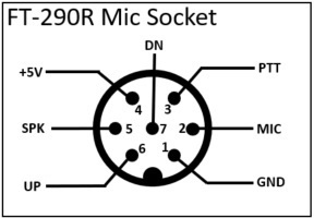
On the FT-290R I am lucky to have +5V available at the microphone socket so I do not even need any dropper resistor or Zener diode. Pin-1 = Gnd, Pin-2 = Mic, Pin-4 = +5V. The total component count is just one PIC12F509, one resistor, one capacitor and a potentiometer. It couldn't be any more simple. The FT-290R uses a DC-coupled IF amplifier chip (μPC577H) that is used as an audio amplifier and there is little or no low-frequency filtering. When I installed this in my old FT-290R it worked first time without any modifications.
VR1 potentiometer will depend on the type of microphone you have. 250kΩ should suit almost any microphone, but be aware that there is 2.2V DC at the output, although the current available is just a few μA. If this is a problem then add a 100nf capacitor in series with the 250kΩ potentiometer. VR1 should be adjusted to give you 20% of the peak modulation depth. For 2.5kHz NBFM this would be 500Hz. The easiest way to set this is to measure the voltage across the speaker of a "virgin receiver" (no CTCSS) to monitor the transmission. Maximum speech-to-tone voltage ratio should be 5:1 as measured on a simple AC voltage multimeter.
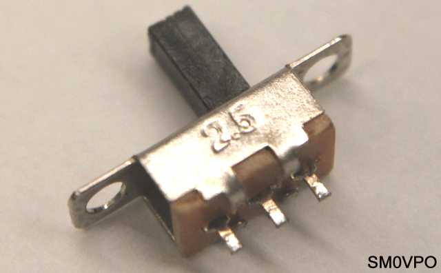
The tone select switch can be any single-pole, 2-way switch. I am using a miniature slider switch robbed from a cheap solar-powered garden lamp. This will fit inside the plastic PTT switch. You will notice that there is no crystal or ceramic resonator used. This simplifies the design greatly and eliminates any components that you need to buy, other than the chip. I found that the internal 4MHz clock is accurate enough for this job. Microchip quote +/- 1% but there is a factory-set OSCCAL value that greatly improves this.
The software is equally simple - toggle an output pin, wait, then toggle it again, wait, then start all over again. The only complication is that I tested the chip pin 4 (GP3) input port to see if it is "1" or "0", and then made a decision to select one of two timing loops. Code costs nothing so I may later extend the code to give a four-tone or eight-tone selection. That can wait until another day.
Since the PIC12-series baseline processors are 8-bit devices, the maximum count is 255. To get lower tones such as 50.0Hz, then the count will be something like 3300 for 50% duty cycle ("1" then repeated for a "0"). Greater than 255 means I have to use two program value bytes and make a 16-bit counter:
Scale - This sets the range (value = 2 to 13)
Count - This fine-tunes the actual tone value
With a Scale value of 13, the generator will cover 49.1Hz to 53.7Hz by adjusting the Count value in 0.015Hz intervals.
After the usual device configuration (switching OFF all the unwanted optional extras), the "guts" of the program is this routine; just six commands:
;**************************** Switch GP0=ON
Main	movlw	b'000001'       ; set w to 1 in bit 0
        movwf	GPIO            ; set GP0 high

;**************************** Test 77/123 select and wait
        btfsc	GPIO,3          ; Test GP3 - skip if 0
        call	Del5		; GOSUB for 123Hz
        btfss	GPIO,3		; Test GP3 - skip if 1
        call	Del6		; GOSUB for 77Hz
This sets pin 7 of the chip to +5v, checks which tone is required and calls the delay loop. This is repeated once more, but it sets pin 7 to 0v for the other half cycle:
;**************************** Switch GP0=OFF
        movlw	b'000000'	; set w to 0 in bit 0
        movwf	GPIO		; set GP0 low

;**************************** Test 77/123 select and wait
        btfsc	GPIO,3		; Test GP3 - skip if 0
        call	Del5		; GOSUB for 123Hz
        btfss	GPIO,3		; Test GP3 - skip if 1
        call	Del6		; GOSUB for 77Hz
This completes both 1/2 cycles of the tone. There are two defferent dalay loops; Del5 (123Hz) and Del6 (77Hz). Each delay loop has two values that you can change to get different tone frequencies: "Count" and "Scale".
The problem I had was that using the conventional "two nested loops" to count, the counting loop only decided how many times the Scale loop was called. This made the frequency steps quite large. Not a problem at 50Hz, but for 250Hz it was not very accurate. I had to find a way of using two timing registers to form a single 16-bit register that I could adjust in 1-count increments.
So now the Dc2 loop contains the high-order count (Count * 256), which is added to the low-order count (Count * 1). Programming is a bit more complicated but it means that any CTCSS tone can be generated with an accuracy of 2 * clock pulses + number of instruction cycles. I also lost a further 6 cycles in the non-variable code, which has to be added to the count value as a correction factor. This means that at (for example) 250Hz, one count makes a 0.4Hz difference, which is within the +/-0.5Hz specification for CTCSS. If I had the time then I could have programmed different values for the "1" and "0" period time delays to give a 0.2Hz accuracy but I felt that would be a bit of unnecessary overkill.
If you want to have different tones other than my chosen 123Hz and 77Hz, then change the Range and Count values. It is just to change the values, assemble and burn the chip. Since these values exist in the HEX file and the HEX file is in ASCII, then you do not even need to change the ASM file and reassemble the program. Just edit the HEX file and program the chip. It is easy to calculate the values for any tone you want using the following formulas:
Scale = 1 + Int(165450/(freq * 256))

Count = 165450/(freq * 256) - Scale * 256 + 6
Here is a worked example, where freq = 77.0Hz.
Scale = 165450/(77.0 * 256) = 8.393364 ; Integer = 8 + 1 = 9

Count = 0.393364*256 +6 = 100.701 -6 = 94.701 (94 is exact value)
Note that the delay loop is called twice, once for each 1/2 cycle, so one iteration of the complete loop looks like this:
;***** Delay loop for 77.0Hz
Del6    movlw   .094        ; Seed Count Lo (Count value)
        movwf   dc1         ; Store it
        movlw   .009        ; Count Hi (Scale value)
        movwf   dc2         ; Store it

Del6a   decfsz  dc1         ; Decrement Lo
        goto    Del6a       ; Repeat if not zero
        decfsz  dc2         ; Decrement Hi, skip if zero
        goto    Del6b       ; Reseed Lo and start again
        goto    Del6c       ; Both zero so return

Del6b   movlw   .000        ; Re-seed Count-Lo register
        movwf   dc1         ; Store it
        goto    Del6a       ; Continue counting

Del6c   retlw   0           ; Done
Notice that I have specified decimal values to load the working register with the Count and Scale values (value preceeded by a decimal point). This makes it simple to calculate using an ordinary calculator (I hate playing maths in hexadecimal on a calculator).
:020000 040000FA
:100000 0025003E0C0600010C260066061009660756
:100010 001D09000C26006606100966071D09030A63
:100020 003C0C3000060C3100F002140AF102190AEF
:100030 001C0A000C3000140A00085E0C3000090C89
:100040 003100F002210AF102260A290A000C3000D0
:040050 00210A000879
:040054 000008000898
:021FFE 00EA0FE8
:000000 01FF
Above is a sample of the 12F509 HEX program file. The values 3C and 06 are hexadecimal for the decimal values 060 and 006 for the 123Hz tone. The values 5E and 09 are hexadecimal values for the decimal values 094 and 009 for the 77Hz tone. You can edit them in NOTEPAD.EXE. I have added spaces so you can see the addresses and data seperated, but the spaces are not present in the file.
Be careful you do not over-write the OSCCAL value (factory clock calibration data). This is one of the problems with the Microchip MPLAB IDE assembler program. I suggest that when you get a blank 12F509 you should read the OSCCAL value. Take a felt-tipped pen and put dots on the eight IC legs to record the last two digits of the OSCCAL binary (HEX) value: Pin 8 for the MSB and pin 1 for the LSB. That way you can always restore the OSCCAL value if you over-write it. I learned this the hard way.
With the code given the minimum Count = 256, which gives a maximum frequency of about 620Hz. For use on the HF bands then you only need a 170Hz frequency difference, so you could program the tones 430Hz and 600Hz for RTTY. If you ";" comment out the Scale delay and use a single counting loop, then the a count of 20 will a maximum frequency of over 7kHz. This means that this same program can be used for AFSK and RTTY, for example an RTTY encoder, or even a modem TX circuit, if you ever feel the need for a bit of 300-Baud or 1200-Baud data transmission. An NE-567 PLL IC will make a good AFSK decoder.
This is how the simplified delay loop looks for 1275Hz:
;***** Delay loop for 1275Hz
Del5    movlw   .127        ; Seed Count Lo (Count value)
        movwf   dc1         ; Store it

Del5a   decfsz  dc1         ; Decrement Lo
        goto    Del5a       ; Repeat if not zero
        retlw   0           ; Done
Once again, if you do not want to edit the assembly code and re-compile a new HEX file, then you edit the RTTY HEX file using notepad and program a new chip. The timing value for any tone from 800Hz to 7kHz is Integer(161925/freq). For example, if you wanted a tone of 1kHz then 161925/1000 = 162. 162 in hexadecimal is A2. But let us look at the correct RTTY values for 1275Hz and 1445Hz.
:020000 040000FA
:100000 0025003E0C0600010C260066061009660756
:100010 001509000C26006606100966071509030A73
:100020 007F0C3000F002120A00086F0C3000F00262
:040030 00170A0008A3
:040034 0000080008B8
:021FFE 00EA0FE8
:000000 01FF
1275Hz count = 127, which is 7F in hexadecimal.
1445Hz count = 111, which is 6F in hexadecimal.
I still have an RTTY program that I wrote in GW-Basic, somewhere. It used the parallel printer port to send and receive serial data to and from the modem. I compiled it into a .EXE file and it will run on MS-DOS and Windows-XP. I will see if I can find it but will not promise anything.
If you are interested on retro modems, the old V.21 300-Baud CCITT modems used a 200Hz frequency shift and had two sets of tones, one for sending and one for receiving. Connecting two modems started with hand-shaking to agree which one had the upper tones and which had the lower tones. By convention the originator always used the low tones to send data. The tone frequencies are:
| Frequency | function | logic level | Power level |
|---|---|---|---|
| 1180 Hz | Uplink | 0 | 0dBm (1mW) |
| 980 Hz | Uplink | 1 | 0dBm (1mW) |
| 1850 Hz | Downlink | 0 | 0dBm (1mW) |
| 1750 Hz | Downlink | 1 | 0dBm (1mW) |
I remember using a V.21 modem to access Bulletin Board Services (BBS) like FidoNet, The Cave, Octopus’s Garden, GNU Pipo and Mycom to download pirate software, pictures and chat. I just sent Hayes "Smartcom" modem codes to COM1 to establish a telephone connection - "ATtention Dial Tone xxx" (AT DT 01234567) on my old Apple][e computer. Those were the days. It was 40 years ago, but seems like only yesterday. In the early 1980's I was in Saudi Arabia where all local calls were free. I think the Internet and FTP killed the BBS.
As usual all my own software is totally free of charge, unless you are going to use it for financial gain. Below is the V3 generator version of files. You can use WinPic.exe to burn the chip - just select the RCD programmer. There is data freely available on the Internet. If you want a chip programming then just contact me and I will see what I can do.
You can easily "lash-up" an RCD programmer by visiting the http://feng3.nobody.jp/en/rcd.html homepage (opens in a new tab). 5 diodes, 1 potentiometer, 4 resistors and a couple of caps can be assembled on a bit of veroboard and used with WinPIC.exe to make a programmer. It is driven and even powered from the computer COM1 port. It also works with a USB to Serial dongle.
Programmer .HEX file: ctcss_pic12f508_ctcss_03.hex.
Programmer .HEX file: ctcss_pic12f509_ctcss_03.hex.
Programmer .HEX file: ctcss_pic12f509_rtty_01.hex.
MPLAB Assembler file: ctcss_pic12c508_ctcss_03.asm.
MPLAB Assembler file: ctcss_pic12f509_ctcss_03.asm.
MPLAB Assembler file: ctcss_pic12f509_rtty_01.asm.
These files can be opened and edited using notepad.exe. Just right-click and download the files, but if you click on them then they will open in a new tab. They are all in 7-bit ASCII.
This has been a really interesting project for me. I was able to do it during my lunch-breaks at work when I am not able to play with antennas or operate the radio outside. I learned a method of programming an 8-bit processor to have a 16-bit counter function. I also learned that the Baseline processors cannot have GP3 programmed as an output port, after a lot of head-scratching.
In addition, the project also opened up a new area of possibilities for me since the project is a low component-count 2-tone generator that can be used for other things, such as AFSK modem, bench test-generator in a pen, the possibilities are limited only by one's imagination. If you have any clever ideas for a 2-tone generator then please feel free to drop me a line, or better still, post a message on my forum at https://sm0vpo.forumotion.com.
In the future I may update the program to select eight pre-selected tones and perhaps include one default of 1275Hz and 1445Hz RTTY tones among them, but I cannot promise anything. I rely on a 70 year old brain and a 25-year old computer that still uses serial and parallel ports. Both can be somewhat un-predictable.
I was recently asked about some of the abbreviations and acronyms I use on my homepages. Perhaps it could be a good idea to add some information about the TLAs and FLAs used on this page.
AFSK - Audio Frequency Shift Keying. An audio tone that cannot decide what frequency it should be
ASCII - American Standard Code for Information Interchange. A standard that varies from computer to computer
CTCSS - Continuous Tone-Coded Squelch System. A system for analogue censorship
CW ident - Carrier Wave Identification. A continuous tone that is continuously interrupted
DIL - Dual In-line. A common Integrated Circuit package favoured by people like me who prefer not to solder SMD chips
FLA - Four/Five-Letter Abbreviation. Often used to confuse newcommers, especially in large companies
PIC - A family of microcontrollers made by Microchip Technology. These seem to have a mind of their own
PLL - Phase Locked Loop (synthesiser). A frequency multiplier based on a frequency divider
RTTY - Radioteletype. Older radio-hams may remember teleprinters, oily rags and WD-40
TLA - Three-Letter Abbreviation. Intended to speed up communication between "experts" and impress people
TTL - Transistor-Transistor Logic. Vintage logic circuits that jumped to conclusions
VRLA - Valve Regulated Lead-Acid. A type of leakproof sealed Lead-Acid battery that sometimes leaks
Very best regards from Harry - SM0VPO
Return to INFO page