
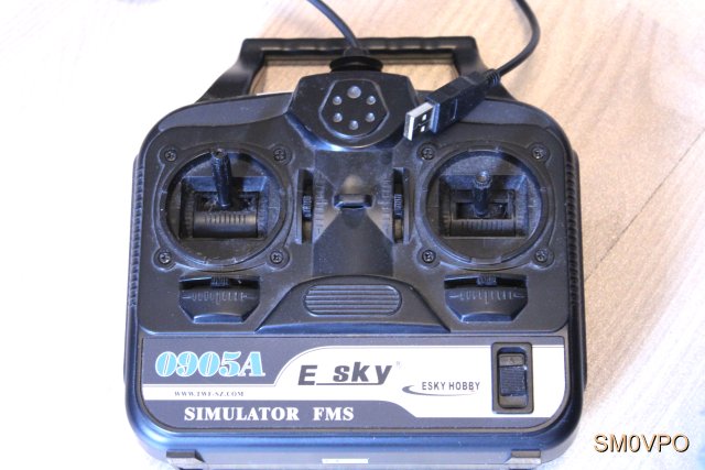
I am still building that 1 metre long Radio Controlled (RC) boat 😉. With home-made radio equipment and a 3D printer I do not need any serious money to build it, either. I have an E-Sky RC simulator (4 channels) that has the RC transmitter box and two joysticks. At $12 it is cheaper than buying ONE spare joystick. That is four channels, and by adding two 5K potentiometers I can have 6 channels. Time to take the old simulator box out of the attic.
In days of old, when knights were bold, and toilets were not invented, I would start laying out a PCB, spraying, curing, exposing, etching, drilling then spend an evening stuffing components on the board. This project deviates from that. If you have the joysticks and pots, all you need in an Arduino Nano, plus the radio transmitter. A $15 PMR walkie-Talkie pair from the toy shop is all you need for the radio side. One on permanent transmit and the other on permanent receive. I tested with a cheap pair that I borrowed. They are supposed to deliver only 0.5-Watts. The range quoted stated "Theoretically 10km" but I do not believe that.
This project describes the Arduino Nano board software and how it is used.
Download and install the Arduino IDE package on you computer, select your device and port number, then you can compile and upload this software. With the Arduino Nano the program is stored in flash RAM, so once it has been programmed, you can disconnect it from your computer. Apply 5-Volts and it will continue running. The Arduino Uno needs to have the script uploaded every time it is powered up, but this is NOT the case with the Nano.
If you have an Arduino Uno then you have six analogue input ports: A0 to A5. With these you can program the Uno for up to 6 proportional channels. The Arduino Nano, on the other hand, has 8 analogue input channels, A0 to A7, so you can use this in an 8-channel RC transmitter. The script in the Script section below is for the 6-channel version, so it will run on both the Uno and Nano. You can program the Arduino Mega for up to 16-Channels, but you will need to extend the encoder frame. See the timing data below.
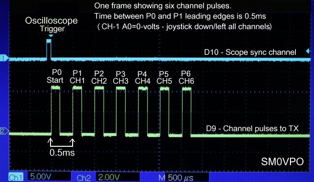
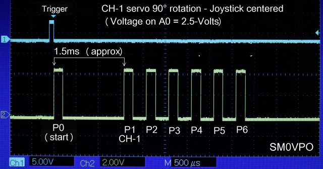
This is rather important. For a commercial 6-Channel "Analogue Proportional RC" system, which is somewhat traditional, there are seven pulses of 100μs. The first pulse starts the RC decoder in the receiver. I will call this pulse P0. After a period of time, the encoder sends a second pulse, P1. The time between the rising edge of P0 and P1 determines the position of the servo in your RC model.
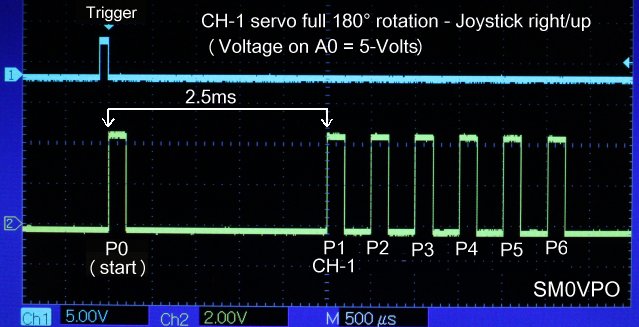
Futaba servos can cost typically $12 for a standard servo. The "traditional" system channel pulse varies from 500μs to 1500μs (0.5 to 1.5 milli-seconds). They have a rotation angle of something like 90° to control your model. Futaba, however, used 500μs to 2500μs (0.5 to 2.5 milli-seconds[ms]) and set a new "standard".
For simple general (27MHz) systems, and most cheaper 2-channel systems (rudder/elevators in aircraft or speed/rudder in boats), the timing was almost always 0.5 to 1.5ms.
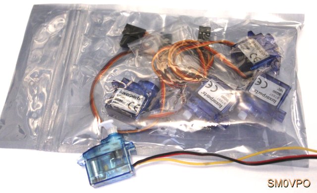
Arduino development servos can cost typically $15 for FOUR miniature servos. The Arduino system channel pulse varies from 500μs to 2500μs (0.5 to 2.5ms), just the same as Futaba, and also have a 180° rotation angle.
Both systems have a 20ms frame length, and there must be 5 milliseconds of idle time (sometimes more) for the analogue receiver to detect the end of frame. This is important.
If you have 20ms frame rate, and need a minimum of 5ms to detect the end of frame, then there is only 15ms remaining for channel information. With the longer Futaba and Arduino systens that use up to 2.5ms per channel, then there is only enough time for a maximum of 6-Channels.
The decoder is nothing more than a counter, like a CD4017B to seperate the channel pulses. Q1 to Q8 have a pulse length for each servo. Q0 is HIGH while waiting for the next frame to start. Every channel pulse keeps a capacitor charged, but the capacitor is discharged with a time-constant of about 4ms. If the capacitor discharges below a specific level then the CD4017B is reset in readiness for the next frame.
This is just a counter. The CD4017B will also support up to 8 channels. Every channel pulse advances the counter to the next output. In this way each output is only HIGH for the duration of the channel timer. This signal is that which the servo expects. The circuit will accept a very low signal of just a few milli-volts of audio pulses. I will be updating this shortly to make the timing more accurate. It was developed in the days when there was more time between frames.
The input circuit is "self biasing", due to the input 47K resistor and the 1μf capacitor that follows the average DC level at the input. The capacitor marked "X" is charged very fast by the channel pulses (through the diode), and the 47K in parallel discharges it. The circuit was designed for a 4 and then 6-channel decoder. If you wish extend the 8-Channel encoder then you may have to reduce the 47K resistor a little (22K or 15K). To check this, set all 8 channels to +5-Volts to generate a "worst case" example. If it resets cleanly with all 8 channels having the longest possible pulse, then it should never give a problem.
In this project I have increased the frame time to 25ms, which means that you can experience the full 8 Analogue channels possible with the Arduino Nano. The servo rotation will be updated 40 times every second. Here are the actual waveforms in one frame:
With other people's Arduino projects it is customary to simply give the script and a wiring diagram. Since there are no components, other than the Arduino in this project, you do not really need a drawing. Instead I have given a connection table, see Pin Connections below. It is also customary to leave you in the dark to figure out for yourself just how the script works, but I will not do that. Here is the complete script for the Arduino:
// Analogue Proportional Radio Control of models - my first real Arduino project
// This code generate anything from 1 to 6-Channels, and can be extended to 8 proportional channels
// Harry lythall - SM0VPO - https://sm0vpo.com for more information

const int outputPin = 9; // Define digital output pin for pulses
const int syncPin = 10; // Define digital output for scope sync
const int joystickPins[] = {A0, A1, A2, A3, A4, A5}; // Define analog input pins for joysticks (up to 8 channels with A6 & A7)
const int minPulseWidth = 240; // Minimum joystick pulse width in microseconds (500μs minus time outside loops)
const int maxPulseWidth = 2220; // Maximum pulse width in microseconds (2500μs minus time outside loops)
const int startPulseDuration = 150; // Start/end pulse duration in microseconds
const int syncPulseDuration = 100; // Sync pulse duration in microseconds (for oscilloscope display)
int timerCalculation = 0;
int timerMilliseconds = 0;
int timerMicroseconds = 0;

void setup() {
  pinMode(outputPin, OUTPUT); // Initialize digital pin 9 as output
  pinMode(syncPin, OUTPUT); // Initialize digital pin 10 as output
  Serial.begin(9600); // Initialize serial communication (for debugging)
}

void loop() {
  // Start of one frame, read joysticks and generate channel pulses
  generateSyncPulse(); // Generate sync pulse (for oscilloscope)
  generateStartPulse(); // Generate frame start pulse
  timerCalculation = 23200; // (25000μs minus processing time outside timing loops - 28750 if 7 or 8 channels)

  // Loop through each joystick
  for (int i = 0; i < sizeof(joystickPins) / sizeof(joystickPins[0]); i++) {
    int joystickValue = analogRead(joystickPins[i]); // Read joystick value
    int pulseWidth = map(joystickValue, 0, 1023, minPulseWidth, maxPulseWidth); // Map joystick value to pulse width
    delayMicroseconds(pulseWidth); // Time delay based on joystick value
    (timerCalculation) = (timerCalculation) - (pulseWidth); // Subtract channel pulse from frame length counter
    generateStartPulse(); // Generate channel-end pulse (start of next channel, or end of frame)
  }

  (timerMilliseconds) = (timerCalculation / 1000); // 25000μs is too big for delay, convert to ms (integer)
  (timerMicroseconds) = (timerMilliseconds * 1000); // How much was lost generating the ms integer (in μs)?
  delay(timerMilliseconds); //Wait the whole milliseconds count
  delayMicroseconds(timerCalculation - timerMicroseconds); // Wait μs increments lost in integer - frame now 25ms (8CH = 30ms)
 }
void generateSyncPulse() {
  digitalWrite(syncPin, HIGH); // Generate sync pulse
  delayMicroseconds(syncPulseDuration); // Sync pulse duration
  digitalWrite(syncPin, LOW); // End sync pulse
}

void generateStartPulse() {
  digitalWrite(outputPin, HIGH); // Generate start/channel pulse
  delayMicroseconds(startPulseDuration); // Pulse duration
  digitalWrite(outputPin, LOW); // End start/channel pulse
}

}
Let us go through the code, step-by-step. With this knowledge you can adjust the code to suit your own system.
const int outputPin = 9; // Define digital output pin for pulses
const int syncPin = 10; // Define digital output for scope sync
const int joystickPins[] = {A0, A1, A2, A3, A4, A5}; // Define analog input pins for joysticks (up to 8 channels with A6 & A7)
const int minPulseWidth = 240; // Minimum joystick pulse width in microseconds (500μs minus time outside loops)
const int maxPulseWidth = 2220; // Maximum pulse width in microseconds (2500μs minus time outside loops)
const int startPulseDuration = 150; // Start/end pulse duration in microseconds
const int syncPulseDuration = 100; // Sync pulse duration in microseconds (for oscilloscopy display)
int timerCalculation = 0;
int timerMilliseconds = 0;
int timerMicroseconds = 0;

void setup() {
  pinMode(outputPin, OUTPUT); // Initialize digital pin 9 as output
  pinMode(syncPin, OUTPUT); // Initialize digital pin 10 as output
  Serial.begin(9600); // Initialize serial communication (for debugging)
}
These two bits of code define all the variables required for the code. I have been generous witht he comments in the code so they speak for themselves.
"const int joystickPins[] = {A0, A1, A2, A3, A4, A5}; // Define analog input pins for joysticks"
This defines the joystick potentiometer ports. The joystick potentiometers are connected across the Gnd and +5V line so that the analogue inputs receive a value between 0V and 5V, representing the joystick position. You can program only A0 for a single channel unit, or add as many channes as you like. I have fixed all the timing issues.
If you want to have a 7 or 8-Channel RC unit (Nano only) then replace "{A0, A1, A2, A3, A4, A5}" with "{A0, A1, A2, A3, A4, A5, A6, A7}". This will reduce the inter-frame rest to only 5ms, which is not very much for the decoder to detect a new frame. You can extend the frame 5ms by changing one parameter;
timerCalculation = 23200; // (25000μs minus processing time outside timing loops - 28750 if 7 or 8 channels)
Now the decoder will have a "fighting chance". The only downside of this is that the servo-refresh time at the receiver will change from 40 times a second to 33.33 time a second. Many older analogue RC systems used a 20ms to 25ms frame length, but this was only exact when all joysticks were centered. As joysticks are manipulated then the frame length varied a little +/- but this has no effect on operation. My code is now totally independent of the joystick movement. I have spent a lot of time on the timing.
  // Loop through each joystick
  for (int i = 0; i < sizeof(joystickPins) / sizeof(joystickPins[0]); i++) {
    int joystickValue = analogRead(joystickPins[i]); // Read joystick value
    int pulseWidth = map(joystickValue, 0, 1023, minPulseWidth, maxPulseWidth); // Map joystick value to pulse width
    delayMicroseconds(pulseWidth); // Time delay based on joystick value
    (timerCalculation) = (timerCalculation) - (pulseWidth); // Subtract channel pulse from frame length counter
    generateStartPulse(); // Generate channel-end pulse (start of next channel, or end of frame)
  }
This creates a loop that repeats for every channel configured. If you have 4 channels, then the joystick pins A0, A1, A2 and A3 will be read and the loop will only run four times. This routine does six things;
  (timerMilliseconds) = (timerCalculation / 1000); // 25000μs is too big for delay, convert to ms (integer)
  (timerMicroseconds) = (timerMilliseconds * 1000); // How much was lost generating the ms integer (in μs)?
  delay(timerMilliseconds); //Wait the whole milliseconds count
  delayMicroseconds(timerCalculation - timerMicroseconds); // Wait μs increments lost in integer - frame now 25ms (8CH = 30ms)
I found that the Arduino is not easy using timers to generate interrupts, and then using timers in the code inside the interrupt timer. So I created a 25000μs variable (frame length) and then subtracted the time used for every analogue channel. This used as the final Frame-Timer value. I couldn't put the end result into a single timer because the Arduino becomes eratic with large values. So I divided it by 1000 (converted to Milliseconds) and used a millisecond timer. The problem with this is that the frame can have a +/-1ms error. So I took the ms integer, multiplied by 1000 (delay milliseconds integer now in microseconds) and subtracted this from the timerMicroseconds variable. So the missing microseconds (less than a ms) are now back in the timerMicroseconds and these are used in a microseconds timer. Yes, it is a bit of a "head scratcher", but it gives a lovely clean and acurate 25ms frame length. No jitter or jumps at all. It also works on both the Uno and the Nano.
void generateSyncPulse() {
  digitalWrite(syncPin, HIGH); // Generate sync pulse
  delayMicroseconds(syncPulseDuration); // Sync pulse duration
  digitalWrite(syncPin, LOW); // End sync pulse
}

void generateStartPulse() {
  digitalWrite(outputPin, HIGH); // Generate start pulse
  delayMicroseconds(startPulseDuration); // Pulse duration
  digitalWrite(outputPin, LOW);
}
The last bits of code are the sync-pulse and channel-pulse generator routines that are called at frame-start.
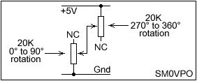
When you use a rotating potentiometer, it will travel from minimum to maximum in 300° of rotation. In this project, channels 5 upwards are therefore not a problem.
If you have a commercial joystick, you will see that they may only have a 90° rotational range, plus a bit extra for the "trim" function, or about 110° in total. You are not going to see the full 5-Volts range. There are a couple of solutions to this:
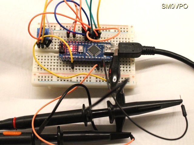
There are no components at all associated with this project, other than an Arduino Nano. All analogue joystick inputs need a voltage 0V to +5V to create the required chanel pulse. The connections to the Arduino are:
| Device pin | Device pin | Designation |
|---|---|---|
| Arduino-Uno D9 | Arduino-nano D9 | Pulses to Transmitter |
| Arduino-Uno D10 | Arduino-nano D10 | Trigger to Oscilloscope |
| Arduino-Uno A0 | Arduino-nano A1 | Channel-1 joystick input 0-5V |
| Arduino-Uno A1 | Arduino-nano A1 | Channel-2 joystick input 0-5V |
| Arduino-Uno A2 | Arduino-nano A2 | Channel-3 joystick input 0-5V |
| Arduino-Uno A3 | Arduino-nano A3 | Channel-4 joystick input 0-5V |
| Arduino-Uno A4 | Arduino-nano A4 | Channel-5 joystick input 0-5V |
| Arduino-Uno A5 | Arduino-nano A5 | Channel-6 joystick input 0-5V |
| N/A | Arduino-nano A6 | Channel-7 joystick input 0-5V |
| N/A | Arduino-nano A7 | Channel-8 joystick input 0-5V |
| Arduino-Uno USB-AB or Socket | Arduino-nano USB-Mini-B | Power input |
Note - Arduino Uno can be powered by 5-Volts at the USB input. It can alternatively be powered through the power socket and an onboard voltage regulator that will accept 12-Volts.
Note - The Arduino Nano must be powered with 5-Volts through the USB connector.
There may be alternative power options, such as injecting to the 5V pins of the boards, but you should check your board data before playing with this. This I have no experience of.
Remember that whatever you do the analogue inputs MUST NEVER be set outside the Arduino power voltages. If you use, for example, Vcc = 3.3-Volts, then this is the maximum voltage that can be allowed at the analogue inputs.
In this project I have tried to give you a simple solution for a multi-channel analogue radio control unit using the Arduino micro-controller. Unlike Arduino projects published by other people I have explained the code so that you can edit or modify as you please to suit your own situation. I posted my prototype code, but now I have fixed all the variable timing issues you have a 100% functional code for up to 6.Channels. You can also extend it to 8-Channels if you change the two bits of code listed in the description.
With this information you can make and program an RC unit for any number of channels, from 1 to 8. If you use the Arduino Mega then you can increase the frame length to 50ms and have up to 16 channels. When I was a kid it was always 2-Channels, unless you were really rich and could afford a 4-Channel unit. My parents would not get me any unit at all.
I hope that this project has given you some "food for thought". You can always e-mail me at harry.lythall@[my domain].com. You can even use oeieio@hotmail.com or hotmail@sm0vpo.com as they are both valid e-mail accounts for me 😉, although I would prefer that you visit my messageboard if you have any questions about this or any other project. I always look forward to receiving feedback, whether it be positive or negative ☺
Very best regards from Harry Lythall
SM0VPO (QRA = JO89WO), Märsta, Sweden.