
Now you are in for a treat. EPROMs may be used for a variety of purposes, as I have shown in the other articles, but did you know that you can generate almost any waveform you want, using an EPROM?. In this project I shall show you how to make a simple AF oscillator that covers 20Hz to 20KHz using an EPROM. You may program it for any waveform you want, this I will also discuss. You can also switch the address line so the EPROM can store several different waveforms, up to 32 different waveforms in the EPROM I have chosen to use, but the circuit shown shows external programing for only 16 different waveforms.
In this application, the EPROM is used to store binary values, which when fed into a Digital to Analogue (D-A) converter will generate a DC voltage proportional to the binary value. The EPROM is addressed by means of a CMOS Voltage Controlled Oscillator (VCO) driving a binary counter. This gives us a continuously counting binary number that will repeatedly change the address of the EPROM. All we have to do is program the EPROM with numbers corresponding to the SINE values and the unit will generate a Sine-waveform.
There are only three ICs used in this project, all of which are dirt cheap:
| CD4046 | - | CMOS PLL - only the VCO used |
| CD4040 | - | CMOS binary divider/counter |
| 2732 | - | EPROM - stores the binary SINE data |
You can of course use any old EPROM you want to use, just change the pin connections to the chip. I chose the 2732 because I have a lot of them "liberated" from old computers. In this project I will only be using 128 bytes (1024 bits) which means that even the 2708 is more than big enough. Ok then, on to the guts of the project.
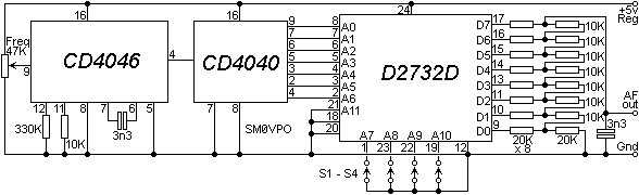
The CD4046 IC is a full PLL synthesiser chip, but here we have ignored the phase detectors, only the VCO is used. The 47K potentiometer varies the VCO-IN pin from 0 to 5v. The 3n3 and 10K resistor set the maximum frequency to 128KHz. The 330K resistor sets the minimum frequency to 6.4KHz. The square-wave output from the VCO is fed into the CD4040 binary counter which counts.
As the CD4040 counts, its output give a repetitive count from 0 to 127 (Decimal) or 00 to 7F (Hexadecimal). Since Q7 onwards is not used, the count then repeats over and over and over again. This repetitive count is used to address each memory cell in the EPROM.
The output of the eprom is an 8-bit binary word from each memory cell. Each binary word represents a sine-wave value at an instant of time. One complete sine cycle occurs after 128 binary words have been outputed. The R2R resistor arrangement at the output of the EPROM translates the binary word into a DC voltage from 0 - 5v.
The EPROM and Divider combination therefore divides the VCO frequency by 128 to give us a frequency range of 50Hz to 1000Hz. The 3n3 capacitor at the output of the R2R ladder smoothes the output a little, otherwise the sine-wave would have steps looking like this:
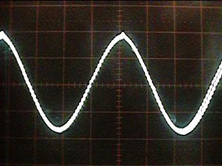
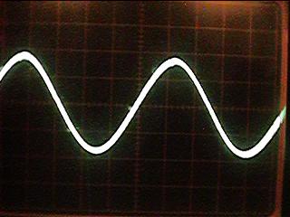
It is the effect of the 3n3 that smoothes out the steps to give an acceptable sine-wave at the output. Without it the waveform would have almost 1% distortion. As long as the output load impedance is high the distortion is typically 0.15% and looks more like this:
The prototype was just thrown together on a bit of blob-board and IC sockets were fitted. That way I can hack it around a lot. I shall be drawing a PCB foil for this project, but like everything else it must wait it's turn. I therefore make no appologies for the seemingly untidy construction shown below:
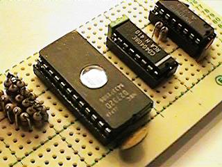
To the left of the picture you can see the R2R D-A ladder. I made it up using 24x 10K resistors to make up the 8x 10K plus 8x 20K resistors. It all works well, two resistors mounted vertically can be twisted/soldered at the top and still take up little more space than a single resistor. 5% resistors all worked fine, in practice there is little variation between resistors that all come from the sme batch.
The 47K Frequency Tune variable potentiometer is mounted external to the board and will eventually sit on the front panel of the box. The PCB foil will have PCB mounted pots, one for frequency control and another for output level using an OP-Amp buffer stage.
Not shown in the circuit diagram is a 22n capacitor between the +5v supply rails of each individual IC. A total of three decoupling caps are required. The unit is fed from a regulated 5v PSU. The good-old 7805 voltage regulator chip works well if the input voltage does not exceed 10v, otherwise it tends to get a bit hot, at least with the EPROM I used.
The circuit as shown operates from about 50Hz to a little over 1100Hz. The two 3n3 capacitors govern this. With 10n capacitors in both positions it will cover 20Hz to 300Hz and with 180p capacitors it will cover 1.5KHz to 20KHz. If you wish to add band switching then you should switch both capacitors. The output level is a constant 5vPk-Pk with the values shown. If the range of the generator is a little wide for you then reduce the value of the 330K resistor. With 330K there is a frequency range of about 20:1 but with 10K that reduces to just 2:1.
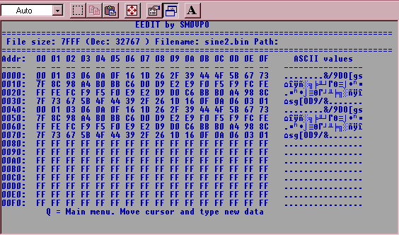
As long as you have access to an EPROM programmer then you can easily calculate the voltage level you want at each of 128 successive points in the waveform. If the level is expressed as a percentage of the waveform level, then multiply the percentage by 2.56 and convert the number to hexadecimal. The value range is 0 to 255 (Decimal) or 00 - FF (Hexadecimal). For example, 2.5vDC is half the supply voltage and therefore 50% of any linear waveform. 50 x 2.56 = 128 (Decimal) = 80 (Hexadecimal) so that location of the EPROM shall be programmed with 80h. Small tip, CALCULATOR.EXE that comes with Micro$oft Windoze has a scientific function. A single click will show a decimal result in Hex.
I have calculated the values you need for a Sine-Waveform and below you can see the screen-capture from my EEDIT program. Here you can download the SINE2.BIN file I created to blow the EPROM (epromosc.zip) and open it with my E-EDIT.EXE program.
In the circuit diagram I have shown four switches, S1 to S4. These select the 16 blocks of 128 bytes in the EPROM. These blocks can be programmed with different values so that the EPROM can be programmed with 16 different waveforms.
| Switches | EPROM address | |||||
|---|---|---|---|---|---|---|
| W/F | S4 | S3 | S2 | S1 | start | end |
| No 01 (sine) | ON | ON | ON | ON | 0000 | 007F |
| No 02 | ON | ON | ON | OFF | 0080 | 00FF |
| No 03 | ON | ON | OFF | ON | 0100 | 017F |
| No 04 | ON | ON | OFF | OFF | 0180 | 01FF |
| No 05 | ON | OFF | ON | ON | 0200 | 027F |
| No 06 | ON | OFF | ON | OFF | 0280 | 02FF |
| No 07 | ON | OFF | OFF | ON | 0300 | 037F |
| No 08 | ON | OFF | OFF | OFF | 0380 | 03FF |
| No 09 | OFF | ON | ON | ON | 0400 | 047F |
| No 10 | OFF | ON | ON | OFF | 0480 | 04FF |
| No 11 | OFF | ON | OFF | ON | 0500 | 057F |
| No 12 | OFF | ON | OFF | OFF | 0580 | 05FF |
| No 13 | OFF | OFF | OFF | OFF | 0600 | 067F |
| No 14 | OFF | OFF | OFF | ON | 0680 | 06FF |
| No 15 | OFF | OFF | ON | OFF | 0700 | 077F |
| No 16 | OFF | OFF | ON | ON | 0780 | 07FF |
There are available Binary rotary switches which can be used to select the waveform numbers you have programmed. Note that the switches are ON to form a ZERO. If using the newer CMOS EPROMS then you my require a 47K pullup resistor to force a ONE when the switch is open.
Well! that's about it. Now you can add your own values to extend the EPROM AF Signal Generator for any waveform you want, no matter how WeIrDe it may be. I hope that you have fun with this project. Very best regards from HARRY, Lunda, Sweden.