

I recently bought 2000 78L05 & 78L10 voltage regulator chips from China for my regulator use/misuse project, but after using my meagre genuine regulators I found that all 2000 new regulators were totally useless. This left me with a few new project ideas that I could not build. So I have decided to make do without them. This short article shows you some of the alternatives I have experimented with.

A Zener diode needs to be reverse-biased so the input voltage, fed through a resistor, will cause the zener to reach it's "avalanch" point, where it conducts. The Avalanch point is that breakdown voltage where the diode conducts and clamps the input to a specific voltage, eg 5.1v.
A conventional power diode (e.g. 1N5401) or a low power switching diode (e.g. 1N4148) can be forward biased and exhibit a near constant voltage drop. They begin to conduct at about 0.7V. This can be used as a 0.7V voltage regulator, just like a Zener diode, but in reverse.

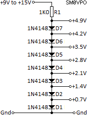
1N4148 diodes can also be put in series to give you multiples of 0.7V, e.g. 1.4V, 2.1V, 2.8V, 3.5V, 4.2V, 4.9V, and so on. Ok, you need a few of them, but they are cheap enough. You can build a simple switched voltage PSU using a rotary switch and a bank of diodes. It is easy enough to mount the diodes on the contacts of a rotary switch. The 1000 1N4148 diodes I bought from China do indeed work, and they work well in this manner.
The signal diode alone will not deliver much current, and is limited by the series resistor: not very efficient. A single BC547 emitter-follower will buffer the voltage(s) to give a more reasonable output current, but at the expense of a 0.7V drop. Adding an extra diode (D0) will make up this loss, give more current, and make a more efficient voltage regulator.
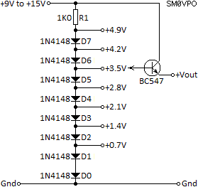
Just a little note of warning here, because these diodes often have a glass case, they are susceptible to light. If you shine a strong lamp through the glass envelope, on the junction, then the voltage changes a little; modulated by the light. If exposed to a flourescent lamp then you can induce 100Hz (120Hz USA) of voltage ripple. So it is best to exclude light in this application. A small dab of black paint, or even a bit of black tape will do the job.

Another small price to pay is that these diodes have a -2mV/°C temperature coeficient, per diode. But for general purpose regulator you can nearly always get away with a little voltage drift. 7400 TTL series, for example, have a +/- 250mV supply voltage tolerance. But in most hobby electronic circuits a stable supply is more important that the exact voltage. your multimeter may display 5.000V but in reality is is calibrated with an internal potentiometer and the true vlotage can be anything from 4.900V to 5.100V, which is a +/- 2% tolerance. I have seen people (QA inspectors) arguing over a digital display of 1.997V when the specification stated 2.0V. Equipment has a tolerance, Quality Insurance inspectors don't ;-)

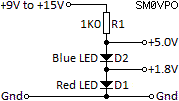
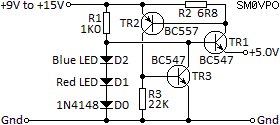
Yes, LEDs. A forward-conducting LED will also make a good Zener diode. You can choose the Zener voltage by selecting the LED colour. A blue LED, for example, will have a voltage drop of about 3.2V and a red LED has a voltage drop of about 1.8V. One red and one blue can be put in series to give you a 5.0V zener diode. Green diodes can give about 2.0V, although these voltages can vary a little, depending on the exact LED you use. A little experimentation can be done to give you exactly what you want.
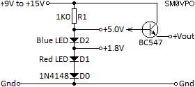
Once more the addition of just one transistor current-buffer transistor can give you up to 100mA, and the addition of a 1N4148 (D0) will give you 5.7V at the diode to deliver a regulated 5.0V out of the regulator. One of the LEDs can be fitted to the front panel of your PSU to act as a power indicator; a dual function.
If you add a pair of transistors to monitor the load current then you can replace the 78L05 and throw the Chinese regulators in the bin where they belong.
| Limiting Current | R2 Resistance Value |
|---|---|
| 50mA | 14 Ohms |
| 100mA | 7 Ohms |
| 100mA | 2.8 Ohms |
| 500mA | 1.4 Ohms |
| 1000mA | 0.7 Ohms |
| 2500mA | 0.28 Ohms |
| 5000mA | 0.14 Ohms |
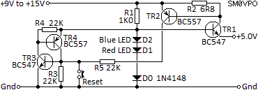
TR1 is the emitter follower that gives you the current. TR2 will conduct if the load current exceeds 100mA, and is set by the value of R2, which in this case is 6.8 Ohms (6R8). 2.8 Ohms will give you 100mA before current limiting. The formula is R = 700 / mA. TR3 is turned on by TR2 and clamps the voltage reference to reduce it in the event of over-current detected by TR2. The 22K resistor prevents any residual leakage current through TR2 causing TR3 to conduct too early. This is perfect for charging batteries. One additional transistor, TR4, can make a latch with TR3 that cuts off the power to the external circuit totally, in the event of an overload. The latch can be reset with a simple momentary short push-button switch (reset).

This is a technique I was shown back in 1965 by my mentor, a radio amateur (G8ABZ). If one connects a diode from the collector to the base of a small-signal transistor, then the collector-emitter will make a very good 1.4V zener diode, due to the voltage drop across the diode, and the B-E junction turn-on voltage, which is also 0.7V. Using a BC547 you can get a 1.4V 100mA Zener diode. Of course, you can add several series diodes or LEDs, to get a higher voltage power zener diode.

Once more you can use several 1N4001 diodes or LEDs to give a higher zener voltage.
Since the B-E junction also has a stable(ish) 0.7V turn-on voltage, then you can connect a preset potentiometer between collector and emitter, and the wiper to the Base junction. Again, the C-E terminals act as a 0.7V zener diode. Adjustment of the potentiometer adjusts the portion of the input voltage that causes the transistor to turn ON. In other words, you now have a variable Zener diode :-)

The only major down-side to this technique is that the potentiometer draws a bit of current, but this must be calculated when you choose the regulator component values. One off-shoot of this is to use this variable diode to bias conventional complementary output stages. You can adjust the potentiometer to get the required standing current through the output transistors.
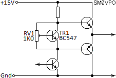
If you want to use the variable diode to build yourself a variable voltage PSU then a simple circuit is shown here. The variable Zener can still be replaced with an LED, or other voltage references to give you a fixed voltage regulator.
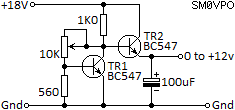
TR1 is the variable diode and TR2 is the current buffer. You do not need a D0 to push the voltage up by 0.7V because the variable zener has a voltage range from 0.7V to 12.7V with the values I have given. The oputput of the regulator is therefore 0V to 12V. Here is the same circuit but with current limiting added.


In all of these circuit the values are standard. Each component, such as the voltage regulator, the 100mA current buffer and the output current limiter can be isolated and put together to form a sort of regulator meccano set. If you need higher current that 100mA then you can use a darlington current buffer and use two D0 diodes in the voltage regulator. A darlington pair has a B-E voltage drop of 1.4V, so two 1N4148's (D0's) (or one D0 in the variable diode circuits) will balance this.

I hope that you have a lot of fun with these ideas and if you should find any other applications or regulator configuration that do not use Zener diodes (or those b¤&@+ing Chinese regulators), then please drop me a line or visit my forum and let us know. If you have any comments or questions about this page then please let me know at my forum.
最好自己做 :-)
Very best regards from Harry Lythall
EA/SM0VPO (QRA = IM86BS)