
Here is a nice little project that I built many years ago, long before I had my own homepages; long before I came to Sweden. I have documented it from memory but I am pretty certain of the values and the circuit.
A similar circuit configuration was used in the late 1970's by Storno and PYE in their communications equipments. Aerotron also used something similar. Storno supplied mainly millitary and PYE supplied mainly police and PMR users. Both users were extremely concerned with battery duration. In those days they powered these sets with DE-AC batteries - remember them? The DEAC is an early NiCad type battery manufactured by the Germany company Varta. They featured low discharge rates and low capacity, so power economy was always a leading topic.
This is an extremely high-gain LF, MF, HF, IF amplifier, suitable for feeding a quadrature FM detector, but I also added an output buffer stage, and then an AGC circuit to drop the gain and make it useable for AM. For FM it does not matter if the signal is limited, in fact it is an advantage. For LW & MW use I also took out TR2 as the IF gain was far too high for the strong AM stations, even radio Luxemburg! there is absolutely no shortage of gain, and there is no magnetic coupling with IF cans or coils to give you self-oscillations. But the project should be built on a good ground-plane. Veroboard is NOT suitable.

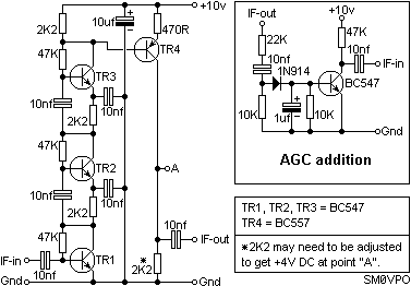
The circuit comprises a simple grounded emitter amplifier stage, which is duplicated in TR2, and again in TR3. All three stages have their power supply feeds cascaded. With signal levels of only a few millivolts it is a waste of power to have a full 10V supply available for just one amplifier. So this circuit configuration has just 3.3V available for each stage, but all stages reuse the same supply current (about 550uA).
In order to feed a conventional diode detector or product detector the 750mV RMS available is not much to play with. I added TR4 to give me a nice solid 2.5V RMS output. It gives a voltage gain of about 5x. In those days I used BC108 transistors and 2N3904 for the PNP devices, but I later changed to BC547 and BC557. Here is the circuit diagram.


The AGC circuit is very clean and clamps the IF output without allowing the amplifier to clip the RF waveform. Adjust the 22K resistor to change the IF output level. Adjust the 2K2 resistor in the IF amplifier to get 4V DC at point "A", but do NOT go below 1K5. This will vary a little depending on the transistor batches, and the individual gains of TR1 - TR3.
In the main IF amplifier I originally used 180K from collector to base but found that with these low voltage some devices needed more current to get them going. If your DC voltages seem a bit strange, especially if you have used alternative transistors, then the following table gives you the correct voltages and which resistor sets it. Once set it should be repeatable for the devices you use.
| Location | Voltage | Resistor to modify |
|---|---|---|
| TR1 Collector | 1.6v DC | 47K TR1 collector to base |
| TR2 Collector | 4.9v DC | 47K TR2 collector to base |
| TR3 Collector | 8.2v DC | 47K TR3 collector to base |
| TR4 Collector | 4.0v DC | 2K2 TR4 collector to Gnd |
Now you should be able to modify the values for just about any device you have. If it is of any interest, the PYE version used 2N4286 (NPN) and 2N4289 (PNP). I cannot remember what Storno used. Aerotron used another 2N variant, but they are an American company and in those days they all used the 2N series.
For SSB or CW you may need to lengthen the AGC hang time. Change the 1uf cap in the AGC add-on circuit.

This little circuit should give you a load of fun and make it possible to make 455kHz and 10.7MHz IF amplifiers without any need for those old IF cans. All you need do is use a crystal or ceramic filter and this little gem. I have also given you all the practical data to modify it to suit alternative transistors you may want to use - we all have our favourite devices :-)
If you are contemplating a VLF receiver then this is excellent. You can maybe increase the capacitor values and use it for AF, but I have never tried this. I have used it for receiving IF via an IR diode. With a sensitivity of typically 1uV it is perfect for getting good optical sensitivity. But you MUST use pleanty of filtering, both optical and IF.
Recent activity on my messageboard prompted me to write this during one sleepless night. If I get another then I may even make up a PCB for it.

Whatever you do, have fun. Very best regards from Harry - SM0VPO
Return to INFO page