
This page is an update to My original heatsinks page but now there is a lot more detailled explanation. I hope that you can get something from it.
My interests in radio and electronics extend from digital, analogue, Radio Frequencies (RF), Audio frequencies (AF), small signal and even projects using high powers. Over the years I have pursued these interests, but always relied on high-power equipment to power my projects, or even design high power equipment.
Power projects often generate a lot of heat, which must to be conducted away from the device generating it. Constructors often consider heat as an unavoidable nuisance and do not actually take much trouble in the design to get rid of the heat. This heat can cause the best of designs to fail when the project is put into service. It is quite common to simply guess at the size of heatsink, get a heatsink that will fit somewhere convenient, then build. I used to be that way myself, but in the late 70s I began using power transistors and the tears began. I had to educate myself. I could not find any mathematical formulas to guide me with heat distribution, power and temperature. So I did loads of experiments and I developed my own formulas for estimating the size of a heatsink needed to keep a project cool.
This article is based on my notes from those experiments, and I hope that sharing with you the results can help you improve your project building, and prevent a catastrophic failure due to lack of care with heat distribution and temperature.
All devices that dissipate power, such as transistors, integrated circuits, resistors, dummy-loads, etc, should not normally be allowed to become much hotter than about 100°C. Most silicon transistors will happily operate hotter, but do not count on it. Most semiconductors, especially Germanium transistors, can change their electrical properties when they get hot. Integrated circuits and transistors drawing current may start to draw even more current due to heat, and the increased power dissipation causes even more current to flow. This "evil circle" is referred to as "Thermal Runaway".
Thermal Runaway can occur in high power circuits where you expect high powers, but even a small RF transistor amplifier delivering, say 50mW of power, can have a small metal case that cannot get rid of the small amount of heat. Just 100mW (0.1 Watts) of total power can seriously kill a small signal transistor when the power causes the temperature to rise beyond the capability of the device.
Project boxes and equipment cases can also contain heat; preventing it from being dissipated elsewhere. A heat-sink on a device will get heat away from the device and protect it, but if the project box has no ventillation or thermal conductivity, then the internal temperature will rise. Your project may work for a few hours continuously, but when the temperature reaches a critical level, something will give way.

Let us take the case of the simple Power Supply Unit (PSU) described elsewhere on my homepages. The PSU may deliver 3 amperes at up to 15 volts at the output. The internal power for the PSU printed Circuit Board (PCB) may be 20 Volts. The basic formula to calculate power is W = A x V (Watts = Volts x Amperes). If you use the PSU to supply a project with 15 Volts at 3 Amperes, then the project is therefore dissipating 3A x 15V = 45 watts. That is actually a lot of heat for an electronic project.
But what is happening inside the power unit?
With a pre-regulated voltage of 20 volts, the regulator transistor has the remaining 5 Volts across it, also at 3 amperes. The transistor is therefore burning 5 V × 3 A = 15 W into heat.
If you now turn the output voltage of the PSU DOWN to 1 Volt, then the load will dissipate 1V x 3A = 3 Watts. BUT the dissipation INSIDE the PSU gets much worse. The series regulator transistor now has 20V - 1V = 19V between Collector and Emitter. It is also conducting 3 Amperes, so it is dissipating 19V x 3A = 57 watts as heat. What do we do with all this heat? - use a heatsink, of course, but how big does that heatsink need to be?
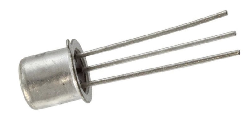
Heatsinks are given a characteristic specification in "Degrees per watt" (usually degrees Celsius), °C/Watt. A TO5 transistor (for example) without a heatsink has a case heatsink characteristic of somewhere in the region of 220°C per watt. So for every watt you make it dissipate it will increase its temperature by 220°C, or about 240 - 250°C at normal room temperatures. That's hot enough to melt solder! We obviously need more metal to soak up and radiate away the heat in order to keep the temperature down. Heatsinks can come in a wide variety of forms, shapes and sizes.
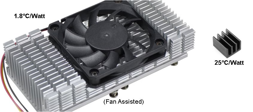
A small transistor dissipating 3 Watts of power, with a 25°C/W specification heatsink, will be cooled to 3W x 25°C plus room temperature (20°C maybe?) = 95°C. With the small heatsink the transistor will therefore survive. The regulator transistor in our 15 Volt power unit will not survive. The heatsink simply conducts heat away from the device and dissipates it into the room, so the larger the surface area, the lower (better) the °C/W rating of the heatsink. So how big must the heatsink be?
Our transistor in the 15 Volt @ 3 Amperes PSU will dissipate a maximum power of 60 watts if the output leads are short-circuited - worst case (and it WILL happen, sooner or later). So to keep the temperature below 100°C we should calculate the smallest heatsink required. The room temperature is assumed to be 20°C, so the transistor can increase its temperature by 100°C minus room temperature = 80°C. 80°C ÷ 60W = 1.333°C per Watt. So you cannot just pick any-old heatsink from the junk-box, or order one from Etsy (an international platform with many sellers based in China).
If you work out the heatsink specification in °C/W (1.333 in the above example), then enter this in this table and click 'Show area' to find the heatsink surface area needed.
| Formula: | Degrees °C/W = 50 / √(Area cm²) |
For our 1.333°C per Watt heatsink, we see that we need almost 1500 cm². A metal sheet of 20cm x 40cm will be perfect (the metal plate has two sides that radiate). But we could have four sheets of 10cm x 20cm, sandwich them and bend up the edges so that it forms fins. See the next section for practical construction. But before we continue with a practical heatsink, let us just take a closer look at that voltage regulator to get a better idea as to how it is connected, and how it works, and why it dissipates power contunuously.
You may be surprised as to just how big a heat-sink you need. Much commercial equipment is under-rated, which may not be a problem for audio use, where a transistor delivers full-power only on occasional peaks. Your 120 Watt guitar stereo amplifier may dissipate up to 200 Watts in the output transistors, but it mostly delivers a sunusoidal waveform where there are only the odd peaks that require full power. If you have a Power Supply Unit (PSU) that is to deliver power continuously, then you need to design your heat-sink for worst-case scenario. So let us look a hypothetical 0-30 Volt variable PSU:
This is only a potentiometer connected to a 'perfect' power transistor base with a current gain of almost infinity (>1,000,000). The base-emitter voltage drop is 0V. As the potentiometer is varied, so the output voltage varies from 0V to 30-Volts, but the transistor has 5 - 35-Volts across it). So how much power will the transistor dissipate as heat? Let us calculate a few random examples and put them in a table:
| Useage | Voltage | TR1 voltage drop | Reg. current | TR1 Dissipation |
|---|---|---|---|---|
| String of Christmas LED lamps | 32V | 35V - 32V = 3V | I = 0.01-Amps | 0.01 x 3 = 0.03-Watts |
| Transistor radio receiver | 12V | 35V - 12V = 23V | I = 0.15-Amps | 0.15 x 23 = 3.45-Watts |
| Charging 24V lorry battery | 27.6V | 35V - 27.6V = 8.4V | I = 3-Amps | 3 x 8.4 = 25.2-Watts |
| Charging 1.2V NiMH (10C) cell | 1.4V | 35V - 1.4V = 33.6 | I = 1-Amp | 1 x 33.6 = 33.6-Watts |
| Charging 12V car battery | 13.8V | 35V - 13.8V = 21.2V | I = 3-Amps | 3 x 21.2 = 63-Watts |
| Charging 6V VRLA battery | 6.9V | 35V - 6.9V = 28.1V | I = 3-Amps | 3 x 21.2 = 84.3-Watts |
| Accidental short-circuit | 0V | 35V - 0V = 35V | I = 3-Amps | 3 x 35 = 105-Watts |
As you can see, the power dissipation demand has a tendency to increase as the PSU output voltage decreases. A simple PSU for 0 - 35-Volts at 0 - 3-Amperes can be continuously put to use for hours, days, weeks, months, or even years with any of the above applications. Charging the 24-Volt lorry battery is much less demanding than charging lower voltage batteries, even less than charging a single NiMH cell for my model boat! The lower the output voltage, so the higher is the voltage drop across TR1. The heatsink is therefore, perhaps, the most important component in a PSU. So let us look more closely at heatsink construction.
You can evaluate home-made heatsinks by using the following formula:
As an example, let us make a heatsink with about 1mm (20 S.W.G.) thick aluminium sheet (copper would be best), folded as shown (viewed from above):
The heatsink is going to be 20cm wide (W), 10cm deep (D) and 12cm high (not shown - viewed from above). Each 'fin' is 10cm x 12cm = 120cm. Each fin also has two sides, area = 240 square cm. There are 10 fins so we have a total of 2400 square cm. The rear plate has also 2 sides x 20cm x 12cm = 480 square cm. Total area = 480 + 2400 = 2880 square cm.
Since and the square root of 2880 = 53.66 we therefore have 50/53.66 = 0.932°C/watt. That would be an expensive heatsink to buy! It may not look pretty home-made, but it works just as well.
It is common practice to use the chassis of a unit as the heatsink, or part of it, but this is limited to a single panel, and steel cabinets are not very good conductors of heat. In addition, the power transistor must be electrically isolated from the metal, which also impairs the heat transfer from the transistor to the heatsink. An aluminium box 5cm x 10cm x 20cm would therefore have an OUTSIDE surface area of 5 x 10 x 20 = 1000 cm². Square root of 1000 = 31.623 so our equipment case has a thermal dissipation of (50/31.623)°C/W = 1.58°C/W Since we need 1.13 °C/W we do not have enough, but we can use the case as a part of the heatsink, and cut down the size of the heatsink we need. Notice that the inside of the case was not taken into account. The case is a closed box so without ventilation the inside of the case will dissipate nothing.
Convection-cooled heat-sinks must be mounted so that the fins, or vanes, are vertical, because warmed air rises. If you mount the heat-sink with the vanes horisontal then there will be little air-flow between the vanes and the heat-sink will not perform as expected.
Let us work backwards using our 15-Volt PSU regulator transistor that is still dissipating over 60 watts without a heatsink. Let us mount it in the 5cm x 10cm x 20cm cabinet we found above. Transposing the formula we have:
We know we need a heatsink of 1.13°C/W so putting this into the formula we get 1957.9 square cm of heatsink required. We already have 1000 in the case, so we must provide the other 960 cm² as vanes, or fins, on the back of the box. 10 fins of 96 square cm (48 per side) will do the job. Each fin can therefore be 5cm x 10cm. Forget the backplane, that is part of the case. 5cm x 10cm is still quite big, but the case is only 5cm deep, so it is reasonable. Including heatsink, the case will now be 5cm x 20cm x 20cm. Note that only the fins were considered.
In reality, a 5cm tall case would be a little small so the case would not be able to accommodate the mains transformer, even if you used three 6.3v 3A filament transformers. Increasing the height of the case by 1cm would reduce the size of the fins by 2cm; 6cm x 8cm (as opposed to 5cm x 10cm earlier).
Imagine, you have just bought a pack of four heatsinks from Temu.com and there is no thermal specification given. The same is true for ALL heatinks sold on Temu.com, Etsy.com, banggood.com, Wish.com and Fruugo.com. Perhaps you have found a heat-sink in your junk box. How can you find out how many degrees temperature rise you will get for one Watt of power? The solution is quite simple, physically measure it and calculate the total exposed surface area and calculate it. The formula is:
Worked example: my heatsink was bought from Temu.com and cost me SEK14 (GB£1.00 or US$1.34). No specification data was given other than it is 40mm x 20mm. Really helpfull (not).
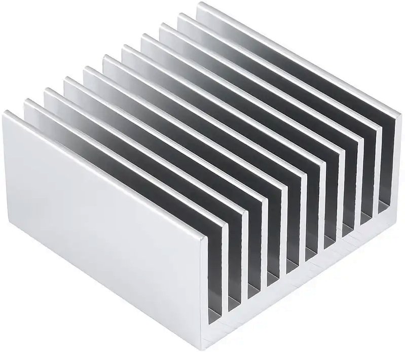
When I measured the heatsink, it was 4cm x 4cm x 2cm. Each exposed fin area is 4cm x 1.7cm (40mm x 17mm).
So there are 11 fins with 22 radiating surfaces. The two end surfaces are 4cm x 2cm = 8cm², but the other 20 are each 6.8cm².
So the total surface area is 20 x 6.8 plus 2 x 8 = 152cm². Entering 152 into the formula above we get 4.0555°C per Watt. So now we know that for only 80°C increase from room temperature (20°C) we will reach a temperature of 100°C with only 20 Watts of power. Note that 100°C is higher than the threshold of pain, so if the heatsink is to be mounted on an equipment case, then it should be a metal case, and the fins mounted vertically.
If bolted this heatsink to the outside rear of my little plastic equipment case I can only tolerate 50°C maximum (20°C room tempeature + 30°C rise in temperature), which limits my little 35 Volt bench PSU to just 7.5 Watts, or 200mA maximum output current (worst case). Ok, I can mount the heatsink on PTFE stand-offs from the plastic, use two heatsinks, and add a fan. Then I can get 1 Ampere, if the fan is powerful enough.
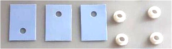
Almost all devices that we need to mount on a heatsink have a metallic surface from which the heat is to be conducted. This surface is usually electrically connected to one of the terminals of the device. We therefore need to place an electrical insulator between the device and the heat sink. In the case of transistors this is in the form of a mica washer or disk. The disk is lubricated with a heat conductive oil to help the heat to be transferred. The oil and the washer should never be omitted if the device is to be effectively protected.
Since aluminium is not the worlds best conductor of heat, I often lay a strip of copper the full length of the heatsink to distribute heat evenly along the complete length of the heatsink. The device is mounted on the copper and the copper distributes the heat to the rest of the heatsink. This avoids a local "hot-spot" where the transistor is thermally connected.
One small suggestion here, look at your local computer shop, second-hand shops that sell boxes of assorted computer bits, or even your local electrical rubbish tip. You may find heatsinks for microprocessors, but if you're really lucky then you may even get something nice and "beefy", perhaps even using water-cooling? This is NOT a long-shot. You would be surprised as to how much electronic "junk" I have recovered and re-purposed. Younger people today are inclined to "throw and buy" instead of re-using or repairing.
I have a full HiFi system with amplifier, speakers, tuner, turntable, twin-cassette, CD player and even a MP3 player/recorder connected to the AUX jacks - all looking like new. I also have a Canon colour laser printer/scanner, with duplexer for double-sided printing (but I had to remove a particularly nasty paper-jam). The MP3 player/recorder module cost me about $4 from Temu, but the rest didn't cost me a cent.
Heat redistribution, calculation, and control techniques form a vast field of study in their own right. There are heat pumps, temperature gradients, junction-to-case thermal resistance, metal conductivity, airflow dynamics, and countless other parameters to explore. Heatsinks are often anodised because a black surface radiates heat more efficiently than a light-coloured one — but don’t be tempted to paint them! Paint forms a lacquer that adds unwanted thermal insulation. Paper and other stickers also give thermal insulation, so the heatsink is a really bad place to put your "Property of ..." sticker.
Even air pressure — and thus air density — affects convective cooling. This becomes especially critical in aircraft, where cabin air density may be only 65% of sea-level conditions, and less than 15% outside at 37,000 feet (about 11 km). In the vacuum of space, of course, there’s no air at all. And even inside a spacecraft, where the air pressure is normal, there’s no gravity — so heated air does not rise!
If the subject of heatsinks were an English country mansion set in 110 acres of gardens, maintained by fifty servants, I’ve merely shown you the doorbell — just enough to get you through the front door (and out of trouble). The rest, dear friends, is a lifetime of discovery — enjoy the journey. 😊
So, that is about all I want to say about heatsinking. Do have fun, but don't get your fingers burned!
Thank you very much for visiting Harry’s Homebrew Homepages and for reading this far. I hope this information has given you some food for thought. You can e-mail me at harry.lythall@[my domain].com, or at hotmail@sm0vpo.com (not a typing error) or british.inteligence.sweden@sm0vpo.com (also not a spelling error 😉). I would prefer you visit my message board if you have any questions. I always appreciate feedback — whether positive or “constructive” 😊