
Hello again all! Lately, I have been experimenting with Off-Centre Fed Dipoles (OCFD). For decades, I was one of those "antenna dinosaurs" who firmly believed a dipole must be perfectly resonant, fed with 50Ω coax, and that you needed a separate dipole for every single band.
However, I have a very limited garden measuring only about 12m x 14m. My multi-band fan dipole currently looks more like an umbrella with the canvas missing! I desperately wanted access to the 7, 14, 21, and 28 MHz bands, but there is clearly not enough space for a full-sized 7 MHz dipole without a little "jiggery-pokery" with the lengths and shape.
On the bright side, I have about 40 meters of clear pathway beside my house along a fence line without any close neighbours; being an end-of-terrace house. This got me thinking about a 25%–75% OCFD to cover all four bands using a single wire. The short end only needs to be about 5.1 meters long, which fits into my garden beautifully.
The catch is that an OCFD requires a 200Ω to 300Ω feed point. This introduces matching problems, along with the nasty habit of common-mode RF travelling back down the outside of the coaxial cable shield right into the radio shack. Thankfully, in this day and age, microphone grilles are made of plastic so you won't burn your lips like in the old days, but I still want to be kind to my neighbours and keep my station clean.
Eliminating RF feedline radiation while getting a solid impedance match without an ATU (or an ATU with only minor corrections) introduces a few BALUN engineering challenges with construction, efficiency, and power handling. This project is my solution: a practical, ultra-low-loss 4:1 BALUN. The idea came to me while lying in bed on one of those sleepless nights.
After loads of trials (and a few errors), I have come up with a cheap, high-performance 4:1 BALUN built in a rather unusual way. The result is surprisingly robust and delivers a fantastic performance; far better than I had ever expected. Because of its unique geometry, it looks exactly like the Starship Enterprise! The design was assisted by Gemini-AI, with whom I chatted frequently to confirm RF theory and discuss practical mechanical layouts. This article is the result, and to be fair, the practicality was a joint effort.
This is a comprehensive article covering various design aspects, so if you want to skip the technical theory and go straight to the construction, feel free to use the chapter links below:

First, let us consider what we are actually trying to achieve with a 4:1 Balun. It is easy to simply wind a couple of coils on a piece of junk-box ferrite and call it a day, but an OCFD places unique demands on a feedline transformer. And since I now use up to 100-Watts, I cannot afford to blasé and allow a couple watts to get an inapropriate ferrite ring warm, even if the result is less than ½ an S-point at the receiving end.
My 25%/75% (20%/80%) dipole is cut fundamentally for 7.1 MHz, but it actually gives its cleanest performance on 14 MHz (my favourite band). At 21 MHz, there is a good match, and at 28 MHz, the performance is more than satisfactory. Crucially, the 28 MHz band is also the worst offender for causing interference to neighbouring consumer electronics.
Therefore, our BALUN must satisfy the following criteria:
There are three primary ways to build an HF balun, each with distinct trade-offs:
| Balun Type | Power Handling | Best For | Main Drawback |
|---|---|---|---|
| A: Current Choke | Excellent (Coax Limit) | Blocking feedline RFI | Isolation drops at lower frequencies |
| B: Voltage Balun | Very Good (Core handles 50%) | Precise 4:1 impedance matching | Does not stop all common-mode RF |
| C: Isolated Transformer | Fair (Core handles 100%) | Total Galvanic Isolation | Heavy, higher losses, prone to saturation |
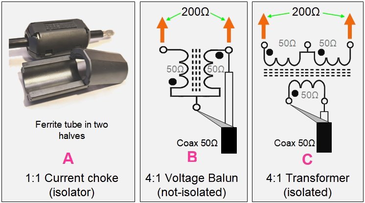
A - 1:1 Coaxial Current Choke (Guanella Choke)
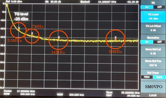
Often called a "Sleeve Choke" or "Choke Balun," this type uses ferrite beads or tubes placed directly over the outside of the coax. It has incredibly low insertion loss because the coaxial cable itself is unbroken; there are no lossy secondary windings because the coax shield forms the inductor. It is dead simple to construct. However, its isolation performance degrades at lower frequencies. On the bench, my 20-bead test line measured an isolation ranging from -1 dB at 1 MHz up to -20 dB at 30 MHz.
B - Voltage-Type Balun (Ruthroff 4:1)
This is perhaps the most common 4:1 balun design. The 50Ω input supplies power directly to one leg of the dipole, meaning the ferrite core only handles the magnetizing current required to "lift" the second leg to the higher voltage. Because the core handles only a fraction of the total throughput flux, the transformer only needs to be magnetically rated for half the applied power (e.g., a 50W core is perfectly fine for a 100W transmitter). This results in exceptionally low insertion loss and a very wide frequency response. Its drawback is that it forces voltage symmetry but doesn't inherently stop common-mode currents from riding down the outside of the feedline.
C - Isolated Transformer Feed
This design provides a physical, galvanic break between the input and output windings. While excellent for blocking low-frequency ground loops, all of the transmitter's RF energy must be converted completely into a magnetic field and back into electricity. The ferrite core must handle 100% of the throughput power, making it heavy, highly prone to saturation, and the most lossy of the three options. Furthermore, its isolation often degrades at higher frequencies because stray capacitance between the primary and secondary windings allows RF to easily bypass the magnetic circuit.
Interestingly, those clip-on computer monitor ferrites are actually an accidental goldmine for radio amateurs! Computer data cables generate high-frequency RF interference (RFI) in the 30–300 MHz range. To suppress this, manufacturers use Nickel-Zinc (NiZn) ferrites (typically equivalent to Type 43 or Type 61). Because they are designed to suppress HF/VHF noise, they make excellent, high-resistivity 1:1 current chokes for our antenna feedlines.
Conversely, the big green power-line chokes and switch-mode PSU transformers are usually made of Manganese-Zinc (MnZn) or iron powder. These are optimized strictly for low-frequency filtering (10 kHz to 1 MHz) to clear out switching power supply noise. While they can work at 1.8 MHz or 3.5 MHz, their losses skyrocket as you move up into the HF spectrum. At low power, you can get away with them simply because their massive physical size absorbs the heat, but at higher powers, they can fail spectacularly.
By the way, the ferrite grade number does NOT have any significance; it is more like a "page number" in the Fair-Rite product catalogue. Fair-Rite did group them loosely by their chemical families:
The HF/VHF Champions: Nickel-Zinc (NiZn)
For general amateur HF use (3–30 MHz), NiZn is the absolute standard. They feature moderate permeability but extremely high electrical resistivity, which keeps eddy-current losses exceptionally low. Common Amidon/Fair-Rite mixes include:
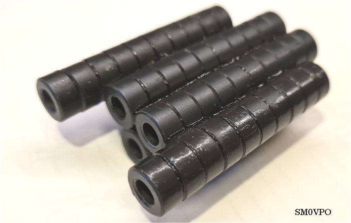
For a previous project, I purchased a bulk pack of 1,000 miniature NiZn beads, part number RND 165-00182 (Mix 43 equivalent). They have an outer diameter of 10mm, an inner hole of 5mm (a perfect snug fit for RG-58 coax), and a thickness of 5mm. They maintain their inductive properties across the entire HF spectrum without breaking a sweat.
Living in an area where local component shops have cut back on hobby electronics, ordering large specialized toroids like an FT-240-43 can be slow and expensive due to postage fees. Using a cluster of these cheap, plentiful 10mm rings allowed me to build an equivalent high-power core using parts I already had on the bench. Important Ferrite Physics Rules-of-Thumb
To create the ultimate OCFD feed system, I decided to implement a Hybrid Design. I combined a high-efficiency 4:1 Ruthroff voltage balun for the impedance match, immediately followed by a high-isolation 1:1 Guanella current choke to stop common-mode feedline currents.
To take this concept a step further, my installation also utilizes an underground "capacitive earth choke." I buried 12 meters of heavy-duty, high-spec LEONI coaxial cable directly under my lawn from the mast to the house. As long as the outer jacket remains completely un-punctured, this forms a massive continuous capacitor with the soil, shunting any remaining shield currents directly to the earth without letting moisture ruin the copper braid. (Just make sure the cable is buried deeply enough so it doesn't get caught in the lawnmower!)
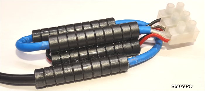
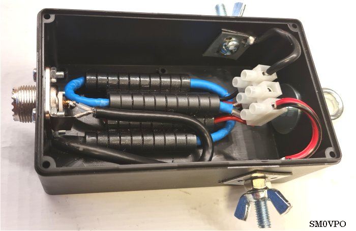
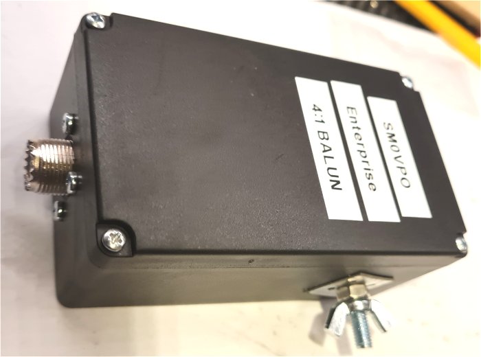
For the masthead unit, the "Enterprise BALUN" is constructed by aligning and gluing together 50 pieces of the RND 165-00182 rings using thin, liquid Cyanoacrylate (Super Glue). Do not use the gel type; the water-thin liquid glue is drawn perfectly between the faces of the ferrites by capillary action, creating a rock-solid brick.
The 50 rings are divided into five distinct tubes (10 rings per tube), arranged in a pattern that perfectly mimics the shape of the Starship Enterprise:
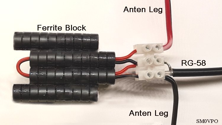
The three primary tubes (the two outer "warp engines" and the lower "engineering hull") form a continuous sleeve choke containing 30 ferrites. The RG-58 feedline weaves up through the left tube, loops around like the Enterprise's "saucer section," passes down through the right tube, and returns up through the centre tube. This clever routing maximizes the physical choke length while bringing the coax interface out right next to the transformer connections.
One major design criterion for the geometry of these three tubes was due regard for the minimum bend radius of the coaxial cable. If you bend a coaxial cable too sharply, you crush the internal dielectric and change the physical spacing between the center conductor and the outer shield. This distorts the cable's internal geometry and ruins its characteristic 50Ω impedance.
As a general rule of thumb for most coaxial cables, the minimum bend radius should be at least 10 times the outer diameter of the cable. For a standard 6mm diameter cable, this means it should never be bent tightly with less than a 60mm radius. Fortunately, RG-58 is a more forgiving and flexible cable, capable of tolerating a bend radius as tight as 20mm (2cm) without causing a significant disturbance to the VSWR. However, 20mm is right at the absolute limit.
By arranging the ferrite tubes into the elongated Starship Enterprise layout, I was able to weave the RG-58 in a smooth, continuous loop that respects this 20mm limit, maintaining the cable's electrical integrity while maximizing the number of choking beads.
The remaining two parallel tubes nested between the engines hold the 4:1 matching transformer. Because of the 60 dB magnetic isolation between adjacent rings, the transformer wires and the coax choke do not interact at all, allowing us to safely house both components inside the same compact, weatherproof enclosure.
The 4:1 transformer uses a simple 1+1 turn bifilar winding. On these (extended) high-permeability cores, a single bifilar turn is more than enough to achieve full coupling from 2 MHz up to 35 MHz, while ensuring that any stray internal resonances are pushed well above 40 MHz where they cannot cause harm. The connections are cleanly terminated onto a 3-pole terminal block inside a plastic box.
Putting the completed assembly on the test bench with an RF analyzer and a tracking generator yielded spectacular results that far exceeded my expectations:
At this point, it is important to share a few details about my test methods and bench constraints. While I do use a cheap Vector Network Analyzer (VNA), I vastly prefer to use a proper Spectrum Analyzer, with a built-in Tracking Generator. This setup provides up to 1 Watt of RF stimulus power. Before testing, the display is carefully "leveled" to normalize the tracking sweep to a flat 0 dB reference line across the entire frequency spectrum of interest (typically 3 MHz to 35 MHz). Because of this calibration, any lossy path introduced between the generator and the analyzer will provide an exceptionally accurate reading—provided a 50Ω impedance is strictly maintained.
For straightforward isolation tests, this 50Ω system is more than adequate, and common-mode sleeve chokes can be verified without any issues. However, measuring insertion loss on a 4:1 voltage balun introduces a classic bench dilemma: the analyzer expects a 50Ω system, but the output of the balun is 200Ω. I could have constructed a second, identical 4:1 balun to step the 200Ω back down to 50Ω for the analyzer's input, but this introduces secondary transformer losses that may not exactly mirror the unit under test, muddying the data.
Instead, I took advantage of how this specific 4:1 Ruthroff configuration functions. In essence, it splits a 50Ω input into two distinct output paths: a "direct feed" leg and a "transformer-shifted" leg. By measuring each leg independently into the analyzer's 50Ω port, I discovered that the direct feed leg showed a microscopic loss of around 0.01 dB at 14 MHz, while the phase-shifted transformer leg showed around 0.31 dB.
When both legs are operating together into a proper 200Ω balanced load, these losses effectively average out to 0.15 dB. Furthermore, when properly matched to 200Ω, the output current passing through each individual winding is halved, meaning the actual real-world copper losses will likely be a "tad" lower still! For impedance matching checks, I used a non-inductive 200Ω resistive load. However, rather than reading standard VSWR, I prefer to measure Return Loss, where the reflected power is expressed in decibels (dB) relative to the forward power.
As a passing technical note: true VSWR measurements are calculated using the ratio of forward and reflected Voltages, not powers. The "V" in VSWR is incredibly important—a fact that many cheap equipment manufacturers and CB operators tend to gloss over. But then again, I am 74 years old and rapidly earning the right to be a bit pedantic in my old age!
There are countless websites across the internet describing the basic mechanics of the OCFD, so I will not delve into the basic theory to any great depth. The traditional concept is usually based on a ½-wavelength wire cut for the lowest desired frequency, with the feed point offset at roughly 33% from one end. This classic 33/67% configuration provides a solid fundamental match on 7 MHz and a very clean harmonic match on 14 MHz (and altered radiation pattern). It should also generally cover 28 MHz. Unfortunately, this standard layout yields its absolute worst impedance match right on 21 MHz—which happens to be one of my bands of interest! At the 33% feed-point the impedance is really high, which could be challenging for an ATU.
To solve this, my plan is to pull the feed point much closer to the edge, placing it at just 20% to 25% from one end. Modeling and theory suggest that this extreme offset should yield reasonable (useable) impedance on 21 MHz, matching my 4:1 "Enterprise" balun beautifully. It should also simultaneously provide a satisfactory match across the 7, 14, and 28 MHz bands. While I expect to do some on-the-air experimentation and trimming once the wire is aloft, the initial return loss should be clean enough to operate without an ATU on most frequencies. As an added bonus, this shorter 20/25% physical leg allows the antenna to fit into my restricted garden layout perfectly.
If you are interested in my reasoning for the OCFD coverage for the four bands: 7 MHz (fundamental), 14 MHz (2nd harmonic), 21 MHz (3rd harmonic) and 28MHz (4th harmonic), here are five diagrams showing the current distribution for each band. The lowest impedance of the dipole is 76Ω where there are nodes at the maximum current (top of the diagrams). These values will all change somewhat due to antenna height, so some experimentation is necessary. For the fundamental frequency, the radiation is broadside to the antenna, but with higher frequencies it starts to migrate towards the axis of the dipole.
In these diagrams I have the horisontal axis as a percentile of the total ½-wave dipole. Different feed-points are shown as A, B, C and D. The impedances to the left are aproximate, but they give you a good idea as to the value, showing how close they are to the curve using a 4:1 Balun.
In the above drawing we see that the ideal feed point for the fundamental is 33% (C), but even 20 - 25% (A and B) should give a useable match. Feedpoint D would be for a "standard" centre-fed dipole.
In the above drawing we see that the ideal feed point for the 2nd harmonic (14 MHz) is 33% (C). Feedpoint D would be for a "standard" centre-fed dipole, which is simply not possible on an even harmonic. But the OCFD makes this a near perfect match.
In the above drawing we see that the ideal feed point for the 3rd harmonic (21 MHz) is about 22% (A-B), but at 33% (C) this will not work since it is a zero-current node (high Impedance). Now this is bad news for me.
In the above drawing we see that the ideal feed point for the 4th harmonic (28 MHz) is about 33% (C). It will work at 20% (A) but NOT 25% (B) since this is also a high-impedance node.
I have included the 5th harmonic, just because it is interesting, especially if you plan to make a 3.5 MHz OCFD. Also note that where a total current nul is shown, this can shift in practice due to several factors, such as velocity factor, which can move the impedance back up the current curve to a useable value at the feed-point.
So from these drawings, we can see that 33% works for 7, 14, and 28 MHz, but (theoretically) not 21 MHz. 20% will work for all bands but there are compromises, and you will need an ATU if you want to get the Return Loss (or VSWR) down. But remember that this is all theory and does not take into account buildings or ground proximity. The thing to do is to test it. In the worse case I can put up a ¼-wave vertial ground-plane antenna for 21 MHz, but I have another idea that may work.
Of course, any seasoned homebrewer needs a backup plan. Every antenna installation is different, and if field testing reveals that the 20–25% feed point introduces unmanageable compromises on the other bands, I have a contingency strategy:
I will simply revert the primary wire back to the "standard" 33% + 66% split to guarantee great native coverage on 7, 14, and 28 MHz. To reclaim 21 MHz band, I will then hang a single, secondary, parallel wire element cut to approximately 16.5% of the total length, connected directly to the feed point alongside the 66% leg. This modification essentially transforms the antenna into a multi-band hybrid OCFD, giving me the best of both worlds: the 33% and 16.5% will fill in the gap(s) to include 21 MHz and (primarily) 14MHz. Note that the lengths will be adjusted on installation, but it is always good to have a little too much and trim.
If you would like to explore the foundational physics and various permutations of this versatile antenna family, the following site is an excellent starting point that features numerous high-quality reference links:
Ham Radio Secrets - Off-Center Fed Dipole
This rather unusual 4:1 hybrid balun completely smashed my expectations (my ghast was flabbered!!). By nesting a low-loss voltage transformer inside a high-isolation sleeve choke using a starship-inspired layout, the insertion losses are significantly lower than I had initially dared to hope for. Now I will be able to get rid of those umbrella spokes that looks as if it's canvas is missing. Since there is less visual impact I can also go back to using multi-strand 230-Volt cables as the radiating elements, which will also increase the radiation efficiency.
It also appears that a "standard" centre-fed dipole will show resonance at ODD harmonics of the fundamental frequency, but the off-centre-fed dipole shows resonance at EVEN harmonics of the fundamental frequency.
If you decide to replicate this 4:1-Blun design, please keep in mind that your junk-box junk may vary. If you use different ferrite rings, they might not feature the same power handling capabilities or high resistivity as the RND 165-00182 Grade 43 material used here. Always test your completed balun at full power on a dummy load first; if you detect any localized heating, then the beauty of this modular gluing method is that you can always scale up the power handling by simply adding more ferrite rings to the starship!
So thank you very much for paying a visit to Harry's Homebrew Homepages and for reading as far as this. I hope that this project has given you some "food for thought". You can always e-mail me at harry.lythall@[my domain].com. You can even use hotmail@sm0vpo.com (not a tipping error) or british.inteligence.sweden@sm0vpo.com (not a spellling error), as they are both valid e-mail accounts for me 😉, although I would prefer that you visit my messageboard if you have any questions about this or any other project. I always look forward to receiving feedback, whether it be positive or "constructive" 😊
This text was also reviewed with the help of Gemini AI, who has become a good friend and mentor in several of my more recent projects. My brother Ron (G0TLA) in England once asked Gemini "Do you know my brother Harry Lythall?". Due to the surprising positive result, it seems that Gemini AI also likes me 😊.
Very best regards from Harry Lythall
SM0VPO (QRA = JO89wo), Märsta, Sweden.