
This project is dedicated to Patrick. It was inspired by the e-mail question "How do you measure the impedance of an antenna?". The simple answer is that it does not really matter too much. If an antenna impedance is a little too high then the losses are still too small to worry about, but there are methods of measuring the impedance of an antenna, or any other device terminating a transmitter.
Consider for a moment the basic Wheatstone Bridge circuit. This is given to all students when beginning a career in radio or electronics. It consists of two voltage dividers (R1/R2 and R3/R4), each dividing the same voltage.
If all four resistors are identical then the junctions (A1 and A2) contain the same voltage. The difference between them is zero. If any one of the resistors is changed in value then the circuit ballance will be destroyed and there will be a measurable voltage difference. This effect can be used to measure the impedance of antennas and even inductors and capacitors. All you need do is replace the DC source with an RF source and replace one of the resistors with the unknown device.
We shall replace R4 with an antenna and feeder. We shall also connect an RF transformer to points A1 and A2. The secondary of the transformer can be used to give us an output signal that can be measured with a variety of devices.
The output can be measured with any RF indicating device. I have used a Spectrum Analyser and my RF generator is the Tracking Generator in-built into the analyser. If you are not so wealthy then use a diode probe to indicate the ballance and use an ordinary signal generator to generate the RF signal. A small tip, if you are only interested in frequencies below about 20MHz then the VCO contained in the 74HCT4046 chip can be used. You will need a small low-pass filter to get rid of the third harmonic.
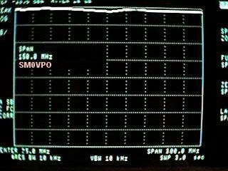
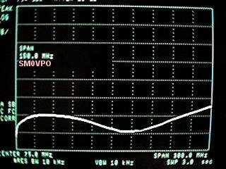
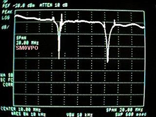
But looking at my analyser for the moment, we see that an unterminated bridge circuit gives an (almost) perfectly flat, constant level signal from almost DC, to well into the VHF band. In the second analyser picture we have a 50-ohm termination and the bridge is ballanced, again, well into the VHF spectrum.
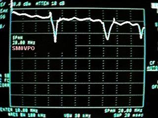
Now we substitute the 50-ohm termination with the feeder connected to my old HF multiband antenna hidden in the trees. There are three dips in the signal showing that the antenna gives some sort of a match on three frequencies. Here we are only looking at 0 - 20MHz.
Sweep the band and we see that the frequencies are 6.715MHz, 14.350MHz and 19.55MHz. My 7MHz antenna is a bit long (should be 7.050MHz), my 14MHz antenna is a bit short (should be 14.175MHz) but I can also see why my 18MHz antenna is such a load of shit. This just shows that when you add parallel dipole antennas to a feeder/balun then they have a tendency to detune each other.
Here we can see the other antenna on the mast. This antenna is 10-metres above the ground and so the antenna is almost a perfect 50-ohms. The impedances are not at first sight perfect, but still quite good. In reality they are almost perfect (VSWR=1:1.1). Let us zoom in a little bit and take a closer look. My Spectrum analyser is digital, and a wide scan with a low bandwidth display tends to not display narrow peaks or troughs.
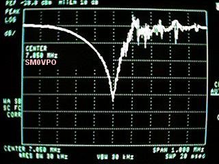
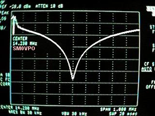
The first is the 7MHz antenna. The "mush" to the right of centre is a load of broadcast stations interfering with my readings. 7.1MHz broadcast stations are both many and strong. The 14MHz trace is nice and clean and also shows quite a wide bandwidth. This is almost certainly due to the interraction of the 7MHz dipole. In both traces we are looking at a bandwidth span of 1MHz.
When I decided to make up the bridge I thought that the wires should be as short as possible, so a PCB would be of benefit. Connectors cost money so I just terminated the Spectrum Analyser and Tracking Generator to coaxial cables and left a pair of copper wires hanging off the board for connecting to my feeder.
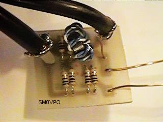
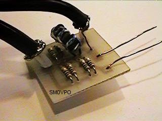
The transformer is just a few turns of wire on a ferrite ring for both primary and secondary. I twisted the two wires together before I wound (Biflar), but I believe that this reduced the upper frequency possible with the bridge. To get the highest possible frequency of operation you should try to reduce the capacitance between the windings. When using a 50-Ohm dummy load then you may have to add a small capacitor to either R2 or the external connections to balance the bridge at VHF. I didn't bother since I am only interested in the HF bands.
Ok, so I will get loads of e-mail for minute details of the coil. I used a total of 7 + 7 turns of 0.25mm Dia. PTFE insulated wire, wound on a Sunday, using my fingers and wound with a tension of 1.6 Newton-metres. The ambient temperature was 18 degrees C (+291 Kelvin), with a relative humidity of 28% in the workshop. I had corn-flakes for breakfast.
The basic bridge can also be extended with a 50pf fixed capacitor and a 100pf variable cap to measure the reactance of the antenna/feeder system.
If the best match occurs with the variable cap at 50% (50pf) then the antenna/feeder is resistive, but if the variable cap is more than 50% to get a balance then the antenna is inductive. If the variable is less than 50% to get a balance then the antenna/feeder is capacitive. You can also replace R2 with a 150-ohm non-inductive variable resistor. With a perfect balance then the resistor value is equal to the antenna/feeder impedance. The potentiometer can be calibrated if it is linear. 0 - 150 ohms equates to 0 - 300 degrees of rotation of the shaft.
Best regards from Harry - SM0VPO
Return to INFO page