
(For ELECTRET MICROPHONE)

The circuit shown is that of a "microphone compressor", i.e., an amplifier circuit which exhibits gain, but continually adjusts that gain to maintain a reasonably constant amplitude output signal, regardless of the amount of signal coming from the microphone itself.
Its uses are many, in the audio field, probably the most common, is in a broadcasting studio (etc) where a constant audio line level is required regardless of whether the announcer's voice be loud or soft. This simple circuit is easy to "get working" and uses readily available components.
The circuit is based on a well-known design, but with modifications: I have chosen for the active circuit element to be a "single supply" Op-Amp LM324, as opposed to the more conventional types which require both a +ve and -ve supply voltage for their operation. This means that this circuit can be of miniaturized construction and may be incorporated into the microphone body itself, it requires only one extra "core" within the microphone cable to run a +12 volt dc supply for the electronics.
I have chosen an "Electret" type microphone insert because of it's small size, excellent frequency response, high output level, availability and low cost. These small "capsules" usually require some sort of foam shroud to suppress microphone "pop". I have not tried any other microphone types i.e., magnetic, ceramic/crystal etc as the Electret has all the above advantages.
The microphone is "AC" coupled to the Op-Amp (the LM324 has 4 separate units within the package, only one is required the others are simply left disconnected, see the manufacturers data sheet for full pin-out information). The amplified output is sampled, rectified and used to charge a capacitor, which sustains a smoothed DC voltage, which is representative of the average signal amplitude.
This voltage is used to control the gate of the "N" channel JFET (types MPF102 /105, J310 and 2N3189 all work) and hence its "ON" resistance. Because the JFET is connected in the feedback path of the Op-Amp, it can be easily seen that the overall circuit gain can thus be "controlled".
I have used "Schotky" type diodes for the voltage doubling rectifier simply because of their low ON-state voltage drop of 290mv, however common small signal silicon diodes, like 1N4148 should work fine as well. The circuit performs best with the on-board local +5v voltage regulator, suitably de-coupled with 2.2uf electrolytic capacitors. Higher supply voltages seem to cause distortion and paralysis on voice peaks? The 47k-ohm resistive voltage divider is used to establish an operating point, connected to the non-inverting input.
The microphone diaphragm is an "Electret" material: an insulating plastic film polarized by a permanent electric charge, produced by heating the film and then placing it in a strong magnetic field. Since the microphone capsule is effectively a small capacitor at audio frequencies, its impedance is extremely high; its output must be fed to (usually) a FET source follower incorporated into the microphone capsule, which acts as an impedance transformer with an output "Z" of a few hundred ohms.
For this reason you must supply DC voltage through an external 10kohm "drain" resistor and ac couple off, the audio signal. The LM324 is a true single supply Op-Amp. To reduce the power supply current drain the amplifiers have a class-A output stage for small signal levels, which converts to a class-B in a large signal mode. For AC applications where the output load is capacitively coupled to the amplifier a resistor (10k) is placed to ground to increase class-A bias current and prevent crossover distortion. With DC coupling there is no crossover distortion.
I have had good results with this design and have used it in my amateur radio station, which then allows me the freedom to walk about, rather than hold the microphone during transmitting!
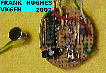
The attached pictures show the authors prototype constructed on a piece of "veroboard", ready for inclusion into microphone housing.
Frank Hughes VK6FH July 2002
If you have any questions related to this project then please refer them to the author Frank V. Hughes.