
The schematic depicts an RF Mixer which uses the 74HC4066 quad analogue switch; configured as a balanced mixer.
The advantagse of the CMOS design over the 'diode' type circuit above are:
If required, the input may be preceded by some form of band-pass filtering, i.e. LC, RF transformer etc, likewise for the O/P. The 4066 behaves like a resistor and thus is not frequency conscious. However, the switching signal for the 74HCxxxx family has an upper limit of 50MHz. Diode ring mixers can produce spurious products due to diode characteristic non-linearity, especially with strong RF inputs; this should not occur with the CMOS switch. The mixer will also respond to harmonics of the LO signal, although with reduced performance. The 4066 IC contains 4 separate switch's of which all are utilized; 'paralleling' reduces Ohmic "ON" resistance to half that of a single unit. A 33k/100k resistive divider provides a 'bias' voltage to the 4066.
The local oscillator (lox), gates ON or OFF, either of a paralleled pair of CMOS analogue switch's and should be a square wave of maximum voltage level = vdd. The 74HC04 buffers the lox and provides the bi-phase signal for the opposite switch.
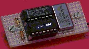
The local oscillator is a TTL type Xtal oscillator module, small in size and readily available in several frequencies. I have used this circuit successfully to up-convert the wide band IF. Output from an ICOM R-8500 communications receiver. From 10.7MHz To 58.7 MHz (48 + 10.7). As the receiver IF. O/P signal level is very low (-60dbm) some amplification is used to precede mixer, (mini-circuits mar6 20db amplifier (not shown in diagram)). The mixer O/P then feeds into a conventional TV receiver (suitably "tuned-in") and becomes a TV "monitor". The tuner section of the TV then acts as a band-pass filter, to the mixer O/P, and the signal is then demodulated for display as video. All tuning is done from the ICOM receiver, audio from the radio itself, and video from the above configuration. The completed unit looks like this:
Although I cannot measure or provide any performance specs for this design, and thereby compare it to conventional designs, the elegant simplicity would suggest that if you have an application then "give it a try"! I should acknowledge, inspiration for the above came from an Electronics & Wireless World magazine' article Feb 98 p138 "multi-band direct conversion receiver" where this type of circuit is used as a synchronous detector in a radio receiver design.
If you have any questions related to this project then please refer them to the author Frank Hughes.