| www.play-hookey.com | Tue, 08-19-2003 | |
| Digital | Logic Families | Digital Experiments | Analog | Analog Experiments | DC Electronic Theory | Optics | Computers | Semiconductors | Test HTML | ||
| Schmitt Trigger |
|---|
Sometimes an input signal to a digital circuit doesn't directly fit the description of a digital signal. For various reasons it may have slow rise and/or fall times, or may have acquired some noise that could be sensed by further circuitry. It may even be an analog signal whose frequency we want to measure. All of these conditions, and many others, require a specialized circuit that will "clean up" a signal and force it to true digital shape.
The required circuit is called a Schmitt Trigger. It has two possible states just like other multivibrators. However, the trigger for this circuit to change states is the input voltage level, rather than a digital pulse. That is, the output state depends on the input level, and will change only as the input crosses a pre-defined threshhold.
In this experiment, we will look at the theory of this circuit's operation, and then build one to demonstrate its real-world operation.

Unlike the other multivibrators you have built and demonstrated, the Schmitt Trigger makes its feedback connection through the emitters of the transistors as shown in the schematic diagram to the right. This makes for some useful possibilities, as we will see during our discussion of the operating theory of this circuit.
To understand how this circuit works, assume that the input starts at ground, or 0 volts. Transistor Q1 is necessarily turned off, and has no effect on this circuit. Therefore, RC1, R1, and R2 form a voltage divider across the 5 volt power supply to set the base voltage of Q2 to a value of (5 × R2)/(RC1 + R1 + R2). If we assume that the two transistors are essentially identical, then as long as the input voltage remains significantly less than the base voltage of Q2, Q1 will remain off and the circuit operation will not change.
Note: Classical analyses of this circuit include the forward current gain, hFE, of the two transistors. This was important in the early days of transistors when a signal transistor was doing well to have a current gain of 30. Modern transistors have a much higher gain (160 for the 2N3904/2N3906, 200 for the 2N4124/2N4126), so they don't have the same limitations as older transistors. We can ignore the effects of transistor base current, although we do still need to account for VBE for the two transistors.
While Q1 is off, Q2 is on. Its emitter and collector current are essentially the same, and are set by the value of RE and the emitter voltage, which will be less than the Q2 base voltage by VBE. If Q2 is in saturation under these circumstances, the output voltage will be within a fraction of the threshhold voltage set by RC1, R1, and R2. It is important to note that the output voltage of this circuit cannot drop to zero volts, and generally not to a valid logic 0. We can deal with that, but we must recognize this fact.
Now, suppose that the input voltage rises, and continues to rise until it approaches the threshhold voltage on Q2's base. At this point, Q1 begins to conduct. Since it now caries some collector current, the current through RC1 increases and the voltage at the collector of Q1 decreases. But this also affects our voltage divider, reducing the base voltage on Q2. But since Q1 is now conducting it carries some of the current flowing through RE, and the voltage across RE doesn't change as rapily. Therefore, Q2 turns off and the output voltage rises to +5 volts. The circuit has just changed states.
If the input voltage rises further, it will simply keep Q1 turned on and Q2 turned off. However, if the input voltage starts to fall back towards zero, there must clearly be a point at which this circuit will reset itself. The question is, What is the falling threshhold voltage? It will be the voltage at which Q1's base becomes more negative than Q2's base, so that Q2 will begin conducting again. However, it isn't the same as the rising threshhold voltage, since Q1 is currently affecting the behavior of the voltage divider.
We won't go through all of the derivation here, but when VIN becomes equal to Q2's base voltage, Q2's base voltage will be:
| VB2 = | 5 + VBE | RC2 | |||
|
|
|||||
| RE | |||||
|
| |||||
| 1 + | RC1 | + | RC1 + R1 | ||
|
|
| ||||
| RE | R2 | ||||
As VIN approaches this value, Q2 begins to conduct, taking emitter current away from Q1. This reduces the current through RC1 which raises Q2's base voltage further, increasing Q2's forward bias and decreasing Q1's forward bias. This in turn will turn off Q1, and the circuit will switch back to its original state.
Three factors must be recognized in the Schmitt Trigger. First, the circuit will change states as VIN approaches VB2, not when the two voltages are equal. Therefore VB2 is very close to the threshhold voltage, but is not precisely equal to it. For example, for the component values shown above, VB2 will be 2.54 volts when Q1 is held off, and 2.06 volts as VIN is falling towards this value.
Second, since the common emitter connection is part of the feedback system in this circuit, RE must be large enough to provide the requisite amount of feedback, without becoming so large as to starve the circuit of needed current. If RE is out of range, the circuit will not operate properly, and may not operate as anything more than a high-gain amplifier over a narrow input voltage range, instead of switching states.
The third factor is the fact that the output voltage cannot switch over logic levels, because the transistor emitters are not grounded. If a logic-level output is required, which is usually the case, we can use a circuit such as the one shown here to correct this problem. This circuit is basically two RTL inverters, except that one uses a PNP transistor. This works because when Q2 above is turned off, it will hold a PNP inverter off, but when it is on, its output will turn the PNP transistor on. The NPN transistor here is a second inverter to re-invert the signal and to restore it to active pull-down in common with all of our other logic circuits.
The circuit you will construct for this experiment includes both of the circuits shown here, so that you can monitor the response of the Schmitt trigger with L0.
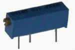
A new component that you will need for this project is a trimmer potentiometer. A potentiometer consists of a resistive element with a movable electrical contact touching it. This permits the potentiometer to serve as a continuously-variable voltage divider.
The figure to the right shows one of the many kinds of potentiometers available for a wide range of applications. This one uses a screw to slowly advance the moving contact along the resistance element. This allows accurate placement of the contact and reduces the likelihood that an accident may move the contact away from the desired position. The particular potentiometer that we will use requires 15 turns of the screw to cover the entire resistance range.
This particular type of potentiometer is typically known as a trimmer potentiometer (or trimpot for short), because it is intended to be adjusted or "trimmed" to a particular setting, and then left there to retain its setting. It will seldom need to be readjusted in normal use.
To construct and test the Schmitt Trigger circuit on your breadboard, you will need the following experimental parts:
Select an area on your breadboard socket that is clear of other circuits. You'll need three adjacent sets of five bus contacts for this project. Then refer to the image and text below and install the parts as shown.


The right-hand side of your breadboard socket should be clear of experimental components as you begin this construction. You'll need about half the space on this end of the breadboard.
Click on the `Start' button below to begin. If at any time you wish to start this procedure over again from the beginning, click the `Restart' button that will replace the `Start' button.
Locate a 0.3" black jumper left over from previous experiments, or else prepare a new one using the same method you have used in the past. Install this jumper on your breadboard socket in the location indicated in the assembly diagram to the right.
Click on the image of the jumper you just installed to continue.
Locate or prepare a second 0.3" black jumper and install it as indicated in the assembly diagram.
Again, click on the image of the jumper you just installed to continue.
Locate or prepare a 0.5" red jumper and install it in the location indicated to the right.
As before, click on the image of the jumper you just installed to continue.
Locate or prepare a second 0.5" red jumper and install it as indicated in the assembly diagram.
Again, click on the image of the jumper you just installed to continue.
Form a 0.2" bare jumper. A clipped component lead is excellent for this application, if you have some available. If not, remove the insulation from the end of a roll of hookup wire and form your jumper from the exposed wire. Install this jumper as indicated in the assembly diagram.
As usual, click on the image of the jumper you just installed to continue.
In the same fashion, form a second 0.2" bare jumper and install it as shown to the right.
Once more, click on the image of the jumper you just installed to continue.
You should have some 1K, ¼-watt resistors (brown-black-red) with their leads already formed to a spacing of 0.5". Located one of these and install it on your breadboard socket in the location indicated in the assembly diagram.
Click on the image of the resistor you just installed to continue.
Locate a new 1K, ¼-watt resistor (brown-black-red) and form its leads to a spacing of 0.4". Install this resistor in the location shown to the right.
Again, click on the image of the resistor you just installed to continue.
Locate one of the 15K, ¼-watt resistors (brown-green-orange) which you have already formed to a lead spacing of 0.5". Install this resistor in the location indicated in the assembly diagram.
Again, click on the image of the resistor you just installed to continue.
Locate a 2.2K, ¼-watt resistor (red-red-red) and form its leads to a spacing of 0.5". Install this resistor in the location shown to the right.
As before, click on the image of the resistor you just installed to continue.
Locate a 3.3K, ¼-watt resistor (orange-orange-red) and form its leads to a spacing of 0.4". Install this resistor in the location indicated in the assembly diagram.
Once again, click on the image of the resistor you just installed to continue.
Locate a second 3.3K, ¼-watt resistor (orange-orange-red) and form its leads to a spacing of 0.4". Install this resistor in the location indicated to the right.
Again, click on the image of the resistor you just installed to continue.
Locate a 2.2K, ¼-watt resistor (red-red-red) and form its leads to a spacing of 0.5". Install this resistor in the location indicated in the assembly diagram.
As usual, click on the image of the resistor you just installed to continue.
Locate a 15K, ¼-watt resistor (brown-green-orange) with its leads already formed to a spacing of 0.5". Install this resistor in the location indicated to the right.
As before, click on the image of the resistor you just installed to continue.
Locate a 1K, ¼-watt resistor (brown-black-red) with its leads already formed to a spacing of 0.5". Install this resistor in the location shown in the assembly diagram.
Again, click on the image of the resistor you just installed to continue.
Locate a 10K, ¼-watt resistor (brown-black-orange) and form its leads to a spacing of 0.5". Install this resistor in the location indicated to the right.
Once more, click on the image of the resistor you just installed to continue.
Locate a 10K, 15-turn trimmer potentiometer (Radio Shack part number 271-343 or equivalent). Note that the pins on this potentiometer are laid out on a 0.1" grid, so it will fit nicely on your breadboard socket. Also note that this potentiometer is constructed so that most of the body will remain above the surface of the breadboard socket. This allows it to clear thin jumper wires, or very nearly so. Install this trimpot in the location indicated to the right, making sure the pins are in the locations indicated by the gold squares in the diagram.
Click on the image of the trimpot you just installed to continue.
Locate an NPN silicon switching transistor (2N3904, 2N4124, or similar) and form its leads as shown here to fit 0.1" spacing. Install this transistor in the location indicated in the assembly diagram. Be careful to observe the indicated orientation of this transistor.
Click on the image of the transistor you just installed to continue.
Locate a PNP silicon switching transistor (2N3906, 2N4126, or similar) and form its leads as shown here to fit 0.1" spacing. Install this transistor in the location indicated in the assembly diagram. Be careful to observe the indicated orientation of this transistor.
Again, click on the image of the transistor you just installed to continue.
Locate an NPN silicon switching transistor (2N3904, 2N4124, or similar) and form its leads as shown here to fit 0.1" spacing. Install this transistor in the location indicated in the assembly diagram. Be careful to observe the indicated orientation of this transistor.
As before, click on the image of the transistor you just installed to continue.
Locate one more NPN silicon switching transistor (2N3904, 2N4124, or similar) and form its leads as shown here to fit 0.1" spacing. Install this transistor in the location indicated in the assembly diagram. Be careful to observe the indicated orientation of this transistor.
Once more, click on the image of the transistor you just installed to continue.
Locate one of the 10" white jumpers you have used in past experiments. Insert one ind into your breadboard socket in the location indicated to the right. Connect the other end to the L0 input.
Click on the image of the jumper you just installed to continue.
This completes the construction of your experimental circuit. Check your assembly carefully against the figure to the right, and correct any errors you might find. Then, proceed with the experiment on the next part of this page.
|
Set your voltmeter to measure positive voltages up to +5 volts. For a digital multimeter (DMM) this is likely to be the 20 volt range. Connect the meter to monitor the variable voltage from the potentiometer. An easy way to do this is to insert a clipped component lead into the breadboard contact column at the left end of the 10K resistor, just to the right of the trimpot, and use a clip lead to connect the voltmeter to this component lead. Of course, connect the voltmeter common lead to ground. Turn on your voltmeter and apply power to your experimental circuit. Note the state of L0 and the output voltage from the potentiometer. Now adjust the potentiometer for an output voltage of 0 volts. At this point, L0 should be off. Increase the potentiometer output voltage. Once past 2.0 volts, continue making your adjustment very gradually, while watching L0. As soon as L0 turns on, stop and note the input voltage on your meter. Record this value to the right, as the positive-going threshhold voltage, VTH+. Increase the potentiometer voltage to +3.0 volts. There should be no change in L0 at this time. Then, gradually decrease the potentiometer voltage while again watching L0. The moment L0 turns off, stop and again note the input voltage indicated on your meter. Record this value in the table to the right, as the negative-going threshhold voltage, VTH-. Repeat these tests several times to verify the threshhold voltages you have already recorded. When you are satisfied that you know how this circuit behaves, turn off your voltmeter and power to your experimental circuit, and compare your results with the discussion below. |
The initial input voltage to your experimental Schmitt Trigger circuit depended entirely on the initial setting of your trimpot. Your experimental circuit simply adjusted itself to that input voltage.
When you set the trimpot to produce an input of 0 volts, L0 was off. Then, as you increased the input voltage past +2 volts, you suddenly saw L0 turn on. In our experimental circuit, this occurred at an input voltage of +2.46 volts. This is slightly less than the calculated value of 2.54 volts for VB2 using these component values.
Of course, the difference of just 0.08 volt, or 3%, could be attributed to resistor tolerances. However, you probably found that the negative-going threshhold was higher than the calculated value. Our circuit exhibited a value of 2.22 volts instead of the calculated 2.06 volts. This is an error of almost 8% from the calculated value, and is due to the fact that the transistors begin to interact before the input voltage actually reaches the current value of VB2.
The key point to note here, however, is that the two threshhold voltages are not the same. Rather, there is a gap between the two, where the positive-going and negative-going ranges overlap. This overlap denotes a property called hysteresis, and it is this property that makes the Schmitt Trigger so useful.
As you observed, even when you were very slowly and carefully adjusting the input voltage to this circuit, the output switching action was sudden and rapid. This is due specifically to the existence of the hysteresis in the circuit. In essence, the positive feedback in the Schmitt Trigger circuit serves to accelerate the transistion from one state to the other, no matter how slow the rise or fall time of the incoming signal. Thus, the Schnidt Trigger serves to "square up" waveforms that have become malformed for some reason, such as extra capacitance in the circuit. It can also take an analog signal such as a sine wave or triangle wave and form it into a digital signal at the same frequency. This is most useful in instruments such as frequency counters, where we can measure the actual frequency of a signal.
Thus, the Schmitt Trigger is a very important circuit in digital electronics.
When you have completed this experiment, make sure power to your voltmeter and experimental circuit is turned off. Remove all of your experimental components from your breadboard socket, and put them aside for use in later experiments.
To see the effect of changing RE (which on your breadboard socket is the left-hand 3.3K resistor, nearer to the trimpot), try replacing it with a 2.7K resistor, and then with a 3.9K resistor. You should find that the smaller the value of RE, the larger the hysteresis gap. However, if you make it too small, you won't be able to turn the output off after turning it on. But at the same time, smaller values of RE allow the Schmitt Trigger output to get closer to ground and logic 0 than higher RE values.
Conversely, larger values of RE narrow the hysteresis gap, until you reach the point where the two threshholds are the same. Beyond this point, you lose all hysteresis and the circuit no longer switches states rapidly for slowly-changing inputs.
In each case, RE has no effect of VTH+; it only affects VTH-. Only the three resistors RC1, R1, and R2 will affect VTH+.
| Your next experiment introduces Basic Clock Sources |
|---|
| All pages on
www.play-hookey.com copyright © 1996, 2000-2003 by Ken Bigelow Please address queries and suggestions to: webmaster@play-hookey.com |